


Quick Research
Generate reliable direction feasibility study reports for your R&D in just a few steps.

Technical Q&A
Discover and master advanced knowledge NOW. Basics, ideas, possibilities, all at once.

Find Solutions
As an expert in R&D theories, this can generate solutions to your technical problems instantly.

Evaluate Feasibility
Analyze your overall solution with one click, know your potential R&D risks in advance.

Monitor Landscape
Get weekly tech updates, stay abreast of the latest tech innovations and key insights.
Power polypropylene or polyethylene pipeline
一种电力管道、聚丙烯的技术,应用在电力及管道领域,能够解决浪费空间等问题,达到节省空间资源、成本低、材料耗用少的效果
- Summary
- Abstract
- Description
- Claims
- Application Information
AI Technical Summary
Problems solved by technology
Method used
Image

Examples
Embodiment 1
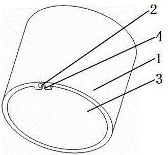
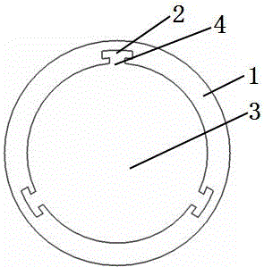
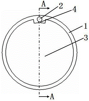
[0029] see Figure 1 to Figure 3 and Figure 5 A polypropylene or polyethylene pipeline for electric power, which is composed of a pipeline wall 1 and a channel 3 enclosed by the pipeline wall, characterized in that the pipeline wall has a self-supporting groove 2, and the inner side of the self-supporting groove has a The connecting channel 3 is connected with the connecting groove 4 of the self-supporting groove. The connecting groove is communicated with the channel, the self-supporting groove is communicated with the connecting groove, the self-supporting groove extends along the direction of the pipe wall, and the connecting groove is also along the direction of the pipe wall. The extension, the width of the connecting groove is smaller than the width of the corresponding self-supporting groove; the power pipeline is an integral structure and is formed in one piece; the diameter of the circle corresponding to the bottom surface of the cylinder where the inner wall of the ...
Embodiment 2
[0032] see Figure 4 , and refer to Figure 1 to Figure 3 and Figure 5, a polypropylene or polyethylene pipe for electric power, basically the same as Example 1, the difference is: the diameter of the circle corresponding to the bottom surface of the cylinder where the inner wall of the pipe wall is located is equal to the cylinder corresponding to the inner edge of the connecting groove. The diameter of the circle on the bottom surface; this structure makes the production of the product more convenient, but the material consumption is more.
Embodiment 3
[0034] see Figures 6 to 8 , a polypropylene or polyethylene pipe for electric power, which is basically the same as Example 1, except that the outer edge of the self-supporting groove is on the same cylindrical surface as the inner wall of the pipe wall; the self-supporting groove is on the same cylindrical surface as the pipe wall. The orthographic projection on the plane perpendicular to the axis of the body is a fan ring, and the gap of the fan ring faces the axis of the pipe wall, and the central symmetry line of the fan ring passes through the center of the pipe wall.
[0035] Figure 8 The suspension wire 51 of the cable 5 in the middle is fan-shaped or rectangular. When passing the cable, the suspension wire 51 and the rib 53 are respectively inserted into the self-supporting groove 2 and the connecting groove 4 at the same time, so that the sheath part 54 of the figure-8 cable is in the channel. , that is, the laying of the cable is completed without the need for oth...
PUM
 Abstract
Description
Claims
Application Information
 - R&D Engineer
- R&D Manager
- IP Professional
- Industry Leading Data Capabilities
- Powerful AI technology
- Patent DNA Extraction
Browse by: Latest US Patents, China's latest patents, Technical Efficacy Thesaurus, Application Domain, Technology Topic, Popular Technical Reports.
© 2024 PatSnap. All rights reserved.Legal|Privacy policy|Modern Slavery Act Transparency Statement|Sitemap|About US| Contact US: help@patsnap.com