Power transmission equipment

A technology for power transmission and equipment, applied in electrical components, cable accessories, cable installation, etc., can solve the problems of difficult maintenance, chaotic cable connectors, large cable volume, etc., to achieve the effect of convenient use and reduced circuit breakage

Inactive Publication Date: 2016-09-21
STATE GRID SHANDONG ELECTRIC POWER CO LONGKOU POWER SUPPLY CO
View PDF5 Cites 9 Cited by
  • Summary
  • Abstract
  • Description
  • Claims
  • Application Information

AI Technical Summary

Problems solved by technology

[0002] Cables for power transmission are connected to each other through cable connectors. When multiple wires form a complex composite cable, the cable connector structure is more, resulting in a larger cable size, and different cable connectors It is inconvenient to distinguish between them, which makes maintenance difficult. At the same time, after the cable connector is used for connection, it is necessary to seal the outside of the cable connector. The existing sealing method is mainly to use complex colloid or other insulating structures for winding way, causing internal cable connectors to clutter

Method used


Image

  • Power transmission equipment
  • Power transmission equipment
  • Power transmission equipment

Examples


Embodiment 1

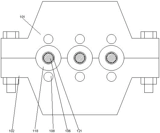
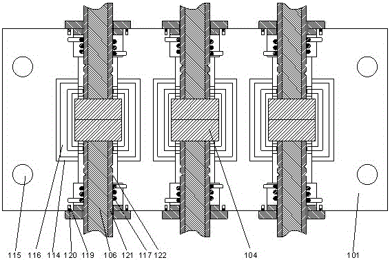
[0028] In this embodiment, in order to improve the sealing performance and prevent moisture from entering the inside of the slot, preferably, corrugated strips 114 arranged at equal intervals are arranged on the outside of the slot 103 of the cover body 101 and the bottom case 102 . The adjacent corrugated bars 114 form a rectangular ring structure, and the corrugated bars 114 on the cover body 101 and the bottom case 102 are staggered from each other.

[0029] After the cover is pressed on the bottom shell, the corrugated bars on the cover are pressed between the corrugated bars of the bottom shell, and the upper and lower card groove structures are sealed by the corrugated bar structure to prevent moisture from passing through the gap between the cover body and the bottom shell The gap between them enters the inside of the card slot and causes a short circuit.

[0030] Further preferably, in order to further improve the sealing performance, in this embodiment, a sealing ring...

Embodiment 2

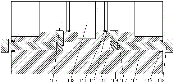
[0032] In order to prevent the cable from being twisted when it is subjected to an external force and cause an open circuit, in this embodiment, a structure for resetting the twisted cable is provided. Preferably, the cable passing slot 105 is far away from the card slot 103 One end is provided with a stepped groove, and a torsion spring 117 is arranged inside the stepped groove, and the torsion spring 117 is sleeved on the outside of the cable 106, and the two ends of the torsion spring 117 are respectively fixed On the inner wall of the stepped groove, an internal thread is provided on the inner wall of the stepped groove, and an end cap 118 is set on the end of the stepped groove away from the wire passing groove 105, and the end cap 118 A through hole with an inner diameter larger than the outer diameter of the cable 106 is provided in the middle, and the cable 106 passes through the through hole.

[0033] In this embodiment, the inner side of the stepped groove is provide...

Embodiment 3

[0036] In the present invention, corresponding mounting holes 115 may be provided on both sides of the cover body 101 and the bottom case 102, and the cover body 101 and the bottom case 102 pass through the The bolts of the mounting holes 115 are connected to each other.

[0037] In this embodiment, in order to improve the sealing effect, preferably, the flanges 112 are at least two groups arranged at equal intervals, and the flanges 112 on the cover body 101 and the bottom case 102 are arranged in a staggered manner. A sealing rubber pad 111 is provided inside the trough formed between the adjacent flanges 112 . After the cover body and the bottom case are installed with each other, tighten the bolts so that the cover body is pressed on the bottom case. When the flange tops on the cover body and the bottom case are pressed on the sealing rubber pad, the sealing effect is better.

[0038] In this embodiment, it is preferable to make the height of the flange equal to the heigh...


PUM


Abstract

The invention discloses power transmission equipment, which comprises cables, a cover body and a bottom shell, wherein the cover body and the bottom shell are symmetric in structure; a plurality of clamping grooves which are arranged at intervals are arranged in the middle parts of the cover body and the bottom shell respectively; the clamping grooves in the inner sides of the cover body and the bottom shell are corresponding in position; two cable connectors are arranged in each clamping groove in the bottom shell; the upper ends of the two cable connectors are clamped into the corresponding clamping groove in the cover body and the lower ends of the two cable connectors are clamped into the corresponding clamping groove in the bottom shell; wire through grooves communicating with each clamping groove are arranged in two sides of the clamping groove; the number of the wire through grooves is equal to that of the clamping grooves; the cables are located at the inner sides of the wire through grooves respectively; and the cables which are corresponding in position are connected to the corresponding cable connectors respectively. By the power transmission equipment, the cable connectors can be distinguished and fixed after the cables are connected, so that the structure is more reliable; and convenience can be carried out more conveniently.

Description

technical field [0001] The present invention relates to a power transmission device. Background technique [0002] Cables for power transmission are connected to each other through cable connectors. When multiple wires form a complex composite cable, the cable connector structure is more, resulting in a larger cable size, and different cable connectors It is inconvenient to distinguish between them, which makes maintenance difficult. At the same time, after the cable connector is used for connection, it is necessary to seal the outside of the cable connector. The existing sealing method is mainly to use complex colloid or other insulating structures for winding way, causing confusion about the internal cable connectors. Contents of the invention [0003] The purpose of the present invention is to provide a power transmission device, which can improve the problems existing in the prior art, and can distinguish and fix the cable connectors after the cables are connected, so...

Claims


Application Information

Patent Timeline
Patent Type & Authority Applications(China)
IPC IPC(8): H02G15/117H02G15/113H02G3/06
CPCH02G3/0683H02G3/0691H02G15/113H02G15/117
Inventor 高菁贾铭坤姜婷婷曲珈萱刘伟张志刚韩杰
Owner STATE GRID SHANDONG ELECTRIC POWER CO LONGKOU POWER SUPPLY CO
Why Eureka
Try Eureka