Permanent magnet reluctance synchronous motor rotor structure having high torque density

A technology of reluctance synchronization and motor rotor, which is applied to synchronous machine components, magnetic circuit shape/style/structure, magnetic circuit, etc., can solve problems such as underutilization, improve utilization rate, increase torque density, reduce The effect of manufacturing costs

Active Publication Date: 2016-09-21
SOUTHEAST UNIV
View PDF4 Cites 19 Cited by
  • Summary
  • Abstract
  • Description
  • Claims
  • Application Information

AI Technical Summary

Problems solved by technology

The maximum value of the combined torque is less than the algebraic sum of the maximum value of the permanent magnet torque and the reluctance torque, resulting in the underutilization of the two torque components

Method used


Image

  • Permanent magnet reluctance synchronous motor rotor structure having high torque density
  • Permanent magnet reluctance synchronous motor rotor structure having high torque density
  • Permanent magnet reluctance synchronous motor rotor structure having high torque density

Examples


Embodiment Construction

[0019] The present invention will be further described below in conjunction with the accompanying drawings.

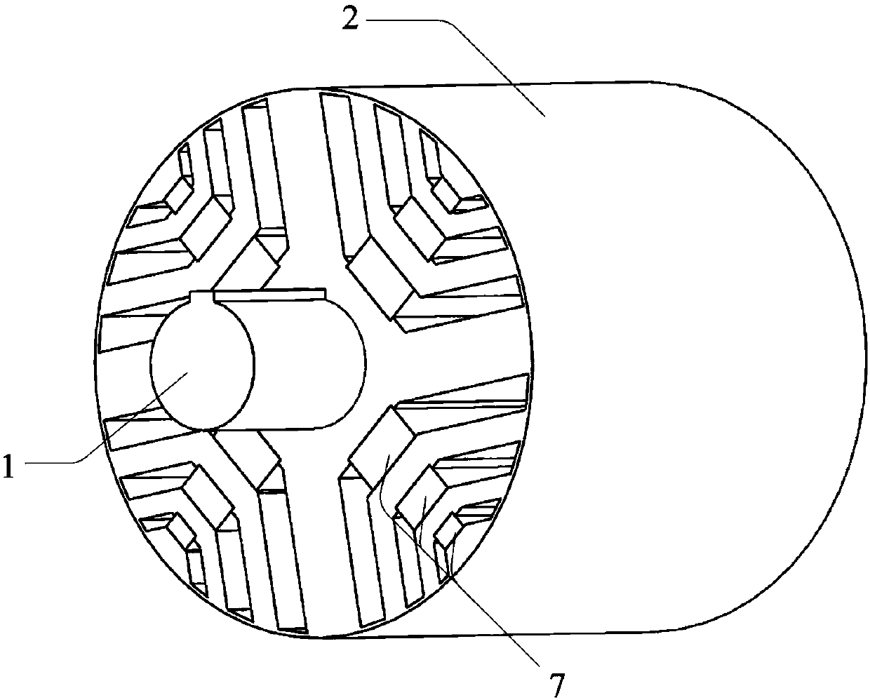
[0020] Such as figure 1 Shown is a high torque density permanent magnet reluctance synchronous motor rotor structure, including a central shaft 1 and a rotor core 2 (made of laminated rotor punches), the central shaft 1 and rotor core 2 are installed on the same central axis ;Around the central axis, P slot groups 3 with the same structural size are evenly arranged on the rotor core 2, and along the clockwise direction, the numbers of the slot groups 3 are sequentially recorded as 1, 2, . . . , i, . ··, P-1, P, where P is the number of magnetic poles of the motor;

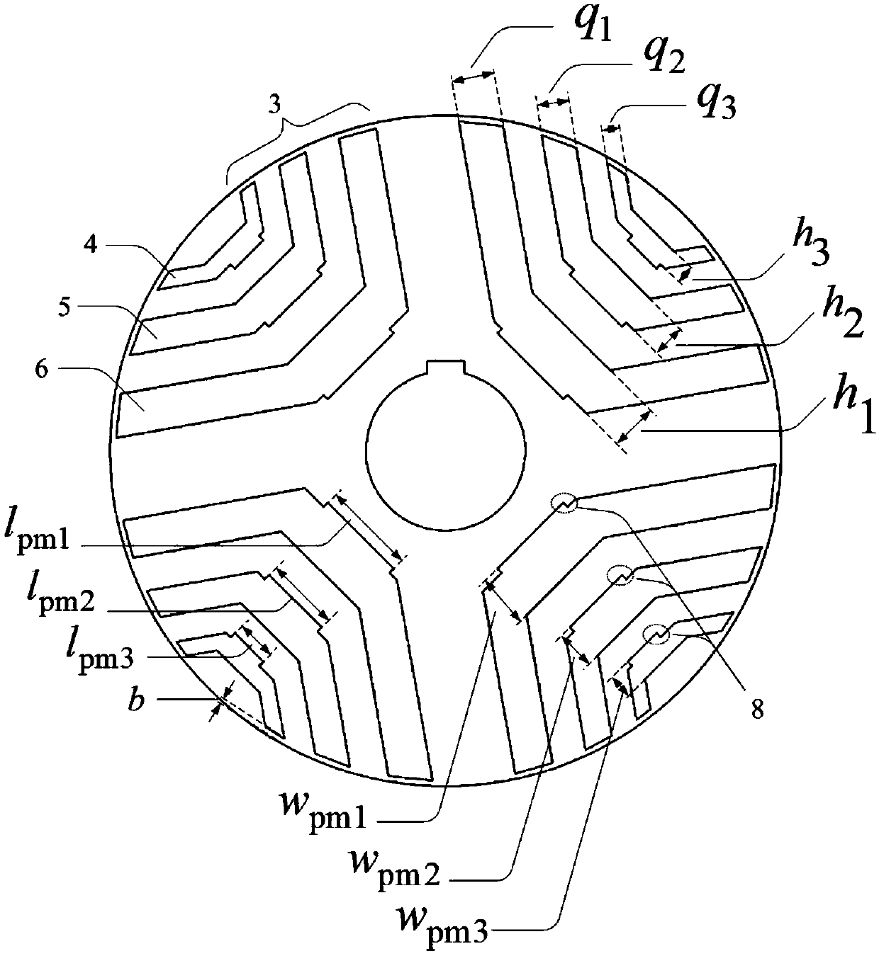
[0021] Such as figure 2 As shown, each slot group 3 includes three U-shaped slots, each U-shaped slot includes a straight base and two straight flanks, and the three straight bases are parallel to each other; according to the distance between the straight base and the central axis The three U-shaped t...


PUM


Abstract

The invention discloses a permanent magnet reluctance synchronous motor rotor structure having high torque density. The permanent magnet reluctance synchronous motor rotor structure comprises a central rotating shaft and a rotor iron core; the rotor iron core is uniformly provided with P groups of through grooves along the circumferential direction; each group of through grooves comprises three layers of U-shaped through grooves arranged in the radial direction of the rotor iron core at intervals; and a permanent magnet is embedded in the straight bottom side of each U-shaped through groove. By means of the permanent magnet reluctance synchronous motor rotor structure disclosed by the invention, the permanent magnet torque component and the reluctance torque component are sufficiently utilized in the synthesis torque of a motor; and thus, the torque density of the motor is increased.

Description

technical field [0001] The invention relates to a high torque density permanent magnet reluctance synchronous motor rotor structure, which belongs to the permanent magnet motor technology. Background technique [0002] Built-in permanent magnet synchronous motors are classified as salient pole motors according to the magnetic circuit structure, and the electromagnetic torque includes permanent magnet torque components and reluctance torque components. Among them, the maximum value of the permanent magnet torque component is reached when the current angle is 0 degrees, and the maximum value of the reluctance torque component is reached when the current angle is 45 degrees. The maximum current angle of the combined torque is between 0° and 45°, it can be seen that the combined maximum torque does not make full use of the two torque components. The maximum value of the resultant torque is smaller than the algebraic sum of the maximum value of the permanent magnet torque and th...

Claims


Application Information

Patent Timeline
Patent Type & Authority Applications(China)
IPC IPC(8): H02K1/27H02K21/10
CPCH02K1/276H02K21/10
Inventor 林明耀孔永
Owner SOUTHEAST UNIV
Why Eureka
Try Eureka