
Wire drives and manipulators

A line drive and drive source technology, applied in the field of online drive devices and manipulators, can solve problems such as inability to transmit tension

Active Publication Date: 2018-01-23
OLYMPUS CORP
View PDF9 Cites 0 Cited by
  • Summary
  • Abstract
  • Description
  • Claims
  • Application Information

AI Technical Summary

Problems solved by technology

That is, if the coefficient of friction is too large, the wire and the input pulley will not slip and slack will occur on the wire. On the other hand, if the coefficient of friction is too small, the wire and the input pulley will slip during traction and large tension cannot be transmitted. question

Method used


Image

  • Wire drives and manipulators
  • Wire drives and manipulators
  • Wire drives and manipulators

Examples


Embodiment Construction

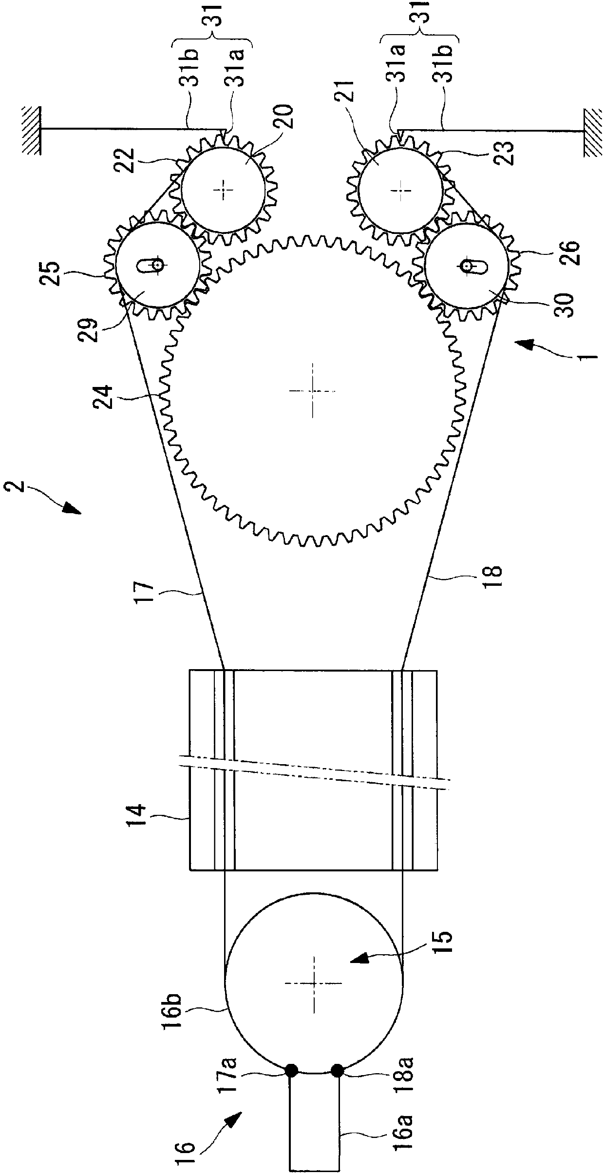
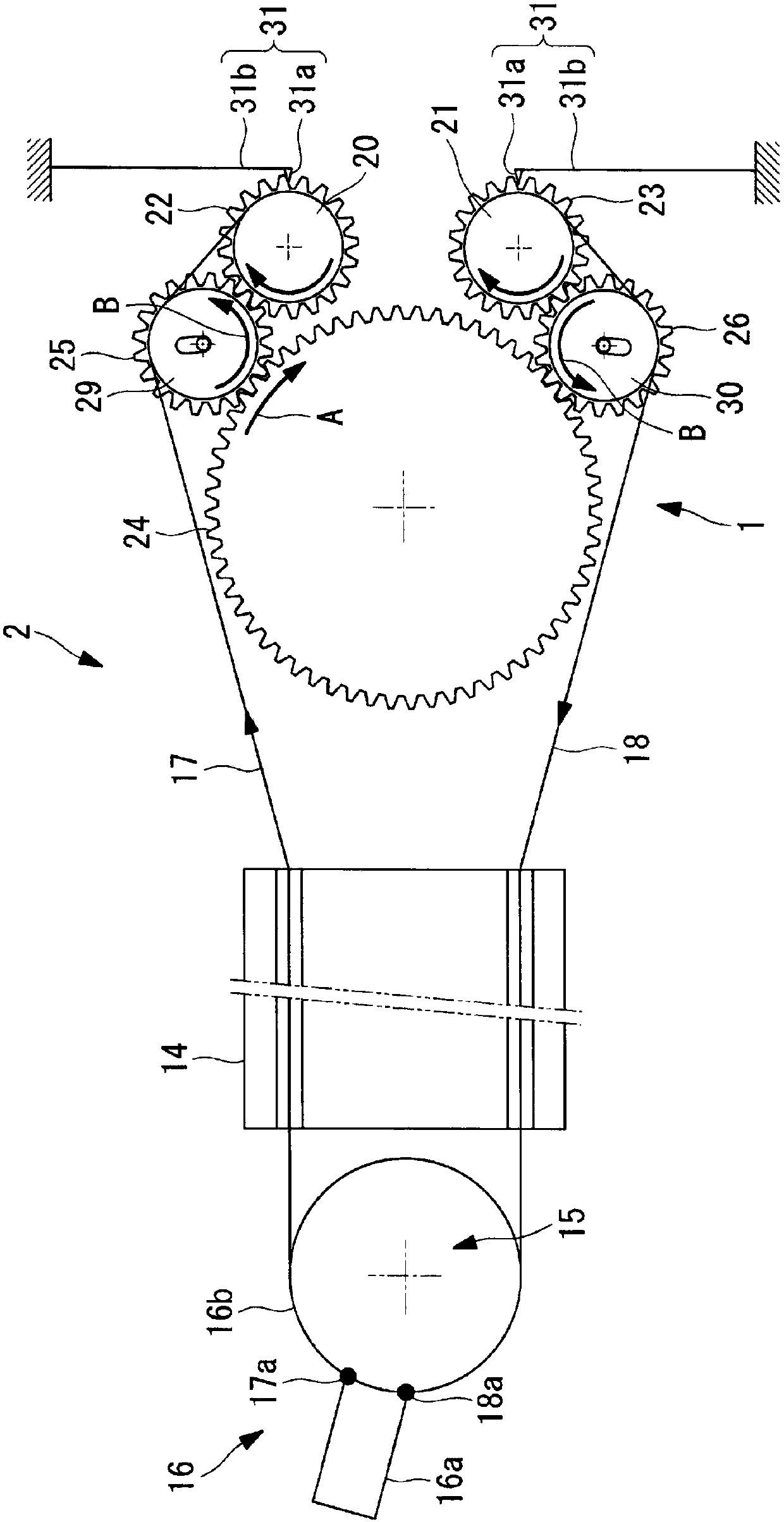
[0042] Next, a wire drive device 1 and a manipulator 2 according to an embodiment of the present invention will be described with reference to the drawings.

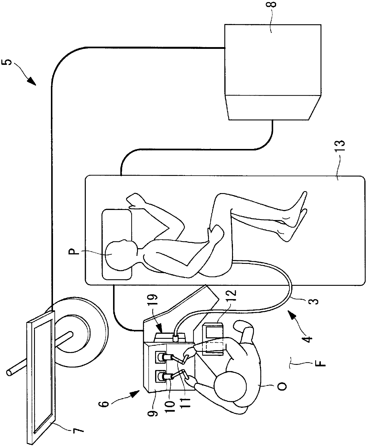
[0043] The manipulator 2 of this embodiment is, for example, a treatment instrument that is introduced into the body through a forceps channel (not shown) or the like included in the insertion portion 4 of the endoscope 3 to treat an affected part or the like. figure 1 The therapeutic manipulator system 5 is shown in use.

[0044] Such as figure 1 As shown, the treatment manipulator system 5 has: an endoscope 3, which has an insertion portion 4 inserted into the body; an operation portion 6, which is operated by an operator O such as an operator to output an operation instruction; a display portion 7, which uses for displaying images acquired by the endoscope 3; and a control unit 8 for controlling the endoscope 3 and the manipulator 2 according to operation instructions.

[0045] Such as figure 1 As shown, the operat...


PUM


Abstract

Slack is compensated for without causing a wire to slip at a pulley. Provided is a wire driving device (1) including: a pair of wires (17, 18) one ends of which are attached to a movable member (16a) and that antagonistically drive the movable member; a pair of pulleys (20, 21) to which the other ends of the individual wires are secured and around which the individual wires are wound; a pair of driven gears (22, 23) that are coaxially secured to the individual pulleys; a drive gear (24) that is connected to a driving source that generates motive power; and a pair of movable gears (25, 26) that are disposed between the drive gear and the individual driven gears and that can transmit the motive power of the driving source to the driven gears from the drive gear, wherein the movable gears are provided in a movable manner so that the movable gears engage with the drive gear and the driven gears when the drive gear is rotated in the direction in which the pulleys take up the wires, and so that the engagements of the movable gears with at least one of the drive gear and the driven gears are released when the drive gear is rotated in the direction in which the pulleys let out the wires.

Description

technical field [0001] The invention relates to a wire drive device and a manipulator. Background technique [0002] Conventionally, there is known a manipulator having a wire drive device that connects a drive source and an output shaft with a wire, and drives the output shaft by tension applied to the wire by the drive source (for example, refer to Patent Document 1 ). [0003] This wire driving device has an input pulley connected to a motor, an output pulley attached to a movable member, a tension pulley, and a wire stretched over these pulleys to counter-drive the output pulley. [0004] The tension pulley uses a spring to apply tension to the wire on the input pulley side to eliminate slack in the wire. [0005] prior art literature [0006] patent documents [0007] Patent Document 1: Japanese Patent No. 4145464 Contents of the invention [0008] The problem to be solved by the invention [0009] However, the wire drive device of Patent Document 1 transmits th...

Claims


Application Information

Patent Timeline
Patent Type & Authority Patents(China)
IPC IPC(8): B25J17/02A61B1/00A61B34/30B25J3/00B25J17/00
CPCA61B1/0016A61B34/30A61B34/71A61B2034/301A61B2034/715B25J9/102B25J9/104A61B1/0057F16H3/20F16H3/30F16H9/10F16H19/005F16H2007/0865
Inventor 岸宏亮
Owner OLYMPUS CORP
Learn More