Furniture sliding rail

A sliding rail and furniture technology, applied in furniture parts, home utensils, drawers, etc., can solve the problems of easy wear and stagnation, large shaking gap, loss of limit function, etc.

Active Publication Date: 2016-09-28
林旭文
View PDF15 Cites 4 Cited by
  • Summary
  • Abstract
  • Description
  • Claims
  • Application Information

AI Technical Summary

Problems solved by technology

The limit stopper of this structure, because the positioning piece is a sheet structure and is also positioned on one side, is very easy to be impacted and deformed, that is, deflected to the inner end, and loses the position-limiting effect.
[0003] Secondly, the ball structure used between the inner, middle and outer guide rails in the above technical solution is generally a single-layer structure. Even if there is a double-layer structure, there are still large swaying gaps and are prone to wear and sticking problems

Method used


Image

  • Furniture sliding rail
  • Furniture sliding rail
  • Furniture sliding rail

Examples


Embodiment Construction

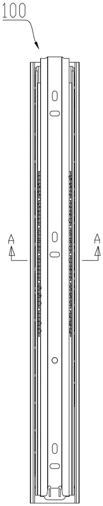
[0058] Drawer parts such as drawers and movable table boards are usually installed in furniture, and in order to provide sliding support for the drawer parts, furniture is provided between the drawer parts and the furniture. rails. Such as figure 1 and figure 2 It is a three-fold retractable furniture guide rail 100 with a new structure applying the technical solution of the present invention, including an outer rail 1 , a middle rail 2 and an inner rail 3 roughly in the shape of a U-shaped groove. The middle rail 2 is axially slidably arranged in the U-shaped groove of the outer rail 1 and the slots of the middle rail 2 and the outer rail 1 have the same orientation, and the inner rail 3 is axially slidably arranged in the U-shaped groove of the outer rail 1. In the U-shaped groove of the middle rail 2 and the notches of the middle rail 2 and the inner rail 3 are facing oppositely; and inner rail 3 sliding inwards so as to be able to limit the sliding stroke of said middl...


PUM


Abstract

The invention relates to a furniture sliding rail. The furniture sliding rail comprises an outer rail body approximately in a U-type groove shape, a middle rail body approximately in a U-type groove shape and an inner rail body approximately in a U-type groove shape. The middle rail body is axially arranged in a U-type groove of the outer rail body in a sliding mode, the directions of groove openings of the middle rail body and the outer rail body are the same, the inner rail body is axially arranged in a U-type groove of the middle rail body in a sliding mode, and the directions of the groove opening of the middle rail body and a groove opening of the inner rail body are opposite; a limiting stopper capable for stopping the middle rail body and the inner rail body from sliding is arranged at the inner side end of the U-type groove of the outer rail body, and therefore the sliding strokes of the middle rail body and the inner rail body in the direction of the inner side end can be limited. The furniture sliding rail is characterized in that the limiting stopper comprises at least one axial standing piece extending in the axial direction; the limiting stopper comprises a buffering soft cushion block, the buffering soft cushion block is inserted into the axial standing piece, and the height of the buffering soft cushion block is larger than or equal to the standing height of the axial standing piece and smaller than the height of the groove bottom wall of the inner rail body. In this way, due to the layout mode that the axial standing piece extends in the axial direction, the impact force bearing capacity of the limiting stopper is improved.

Description

technical field [0001] The invention belongs to the technical field of hardware products for furniture, and in particular relates to a slide rail for furniture. Background technique [0002] Pull-out parts such as some drawers and movable platens are usually installed in the furniture. The most original solution is to use the roller guide rail solution, which is also the most used solution in ordinary furniture at present. Later, the ball guide rail solution was developed. These ball guide rails are mainly divided into two-section ball guide rails and three-section ball guide rail solutions. The earliest two-section ball guide rail we can find is a ball-type drawer guide rail disclosed in a utility model patent named "Ball Drawer Guide Rail" with application number 01242280.0, which is characterized by a symmetrically opened four ball grooves. The inner guide rail is arranged longitudinally on the top of the other side of the bracket. There are several installation holes on...

Claims


Application Information

Patent Timeline
Patent Type & Authority Applications(China)
IPC IPC(8): A47B88/10A47B88/16A47B88/493
CPCA47B2210/0002
Inventor 林旭文
Owner 林旭文
Why Eureka
Try Eureka