
Plate Rolling Bending Machine

A technology for bending machines and plates, applied in metal processing equipment, feeding devices, positioning devices, etc., can solve problems such as inconvenient use, and achieve the effects of improving forming effects, high precision, and reducing deformation and springback

Active Publication Date: 2017-11-24
江西荣妍科技有限公司
View PDF7 Cites 0 Cited by
  • Summary
  • Abstract
  • Description
  • Claims
  • Application Information

AI Technical Summary

Problems solved by technology

However, the working width of the roll bending machine in the prior art is usually consistent with the width of the plate to be bent and is fixed
Therefore, when it is necessary to change the width of the finished metal sheet, it is necessary to increase or modify the rolling bending machine, which is inconvenient to use

Method used


Image

  • Plate Rolling Bending Machine
  • Plate Rolling Bending Machine
  • Plate Rolling Bending Machine

Examples


Embodiment Construction

[0026] The technical solutions in the embodiments of the present invention will be clearly and completely described below in conjunction with the accompanying drawings in the embodiments of the present invention. Obviously, the described embodiments are only a part of the embodiments of the present invention, rather than all the embodiments. Based on the embodiments of the present invention, all other embodiments obtained by those of ordinary skill in the art without creative work shall fall within the protection scope of the present invention.

[0027] It should be noted that when a component is said to be "fixed to" another component, it can be directly on the other component or a central component may also exist. When a component is considered to be "connected" to another component, it can be directly connected to another component or there may be a centered component at the same time. When a component is considered to be "installed on" another component, it can be directly in...


PUM


Abstract

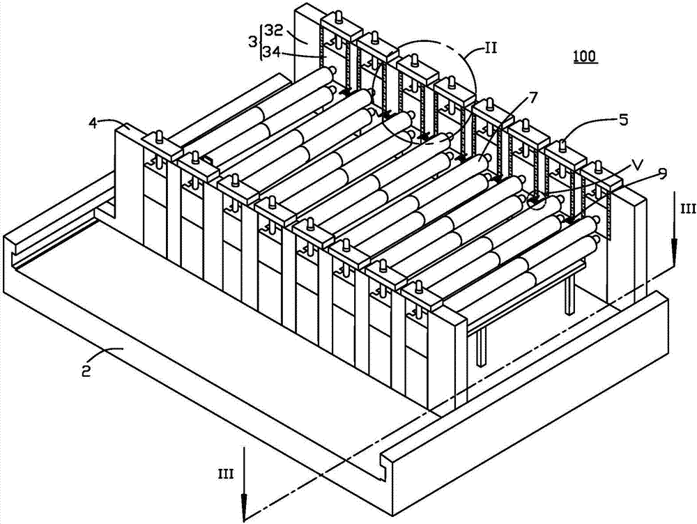
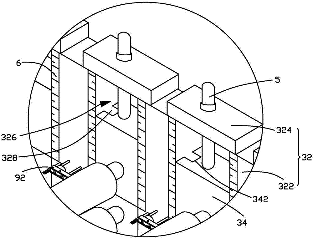
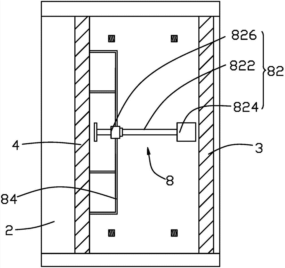
The invention provides a plate rolling and bending machine. The plate rolling and bending machine comprises two opposite supporting walls, a plurality of forming roller sets arranged in the conveying direction of a plate at intervals, a base, a screw rod driving mechanism and a connecting rod, wherein one supporting wall is fixed to the base, and the other supporting wall is movably installed on the base. Each forming roller set comprises an upper roller and a lower roller, the upper roller and the lower roller are oppositely arranged in the vertical direction, and each of the upper roller and the lower roller comprises a telescopic shaft and a roller body fixedly arranged on the telescopic shaft in a sleeving mode. The screw rod driving mechanism comprises a screw rod, a motor driving the screw rod to rotate and a screw rod nut connected to the screw rod in a screwed mode. The connecting rod is connected to the screw rod nut and the supporting wall movably installed so that the two supporting walls can get close or get away from each other, the distance between the two supporting walls can be adjusted for adapting to the bending operation of plates of different widths through the telescoping motion of the telescopic shafts of the forming roller sets, and use is convenient.

Description

【Technical Field】 [0001] The invention relates to the technical field of metal forming, in particular to a plate rolling and bending device. 【Background technique】 [0002] The sheet metal rolling press brake is an equipment for bending sheet metal. It includes two support plates and a roller assembly that rotates on the two support plates. The shape of the finished sheet is determined by a roller that is compatible with its size. The components are rolled and formed, and the width of the finished sheet is adapted to the working width of the rolling press brake. However, the working width of the prior art rolling press brake is usually the same as the width of the plate to be bent, and is fixed. Therefore, when the width of the finished sheet metal product needs to be changed, it is necessary to increase or modify the rolling press brake, which is inconvenient to use. [Content of the invention] [0003] In view of the above-mentioned problems, it is necessary to provide a plate ...

Claims


Application Information

Patent Timeline
Patent Type & Authority Patents(China)
IPC IPC(8): B21D5/08B21D43/00
CPCB21D5/002B21D5/08
Inventor 苏俊宇
Owner 江西荣妍科技有限公司
Learn More