Servo turning machine

A technology of turning machine and reducer, applied in the field of servo turning machine, can solve the problems of low degree of automation, inaccurate positioning accuracy, slow turning speed, etc.

Inactive Publication Date: 2018-05-11
LIUZHOU GAOHUA TECH CO LTD
View PDF6 Cites 0 Cited by
  • Summary
  • Abstract
  • Description
  • Claims
  • Application Information

AI Technical Summary

Problems solved by technology

Most of the turning devices currently on the market can only rotate at a fixed angle, and the applicability is relatively low. The positioning accuracy is not accurate enough when the turning equipment clamps the workpiece, and the turning speed is slow, and the automatic turning mechanism rarely appears on the automatic production line of small stamping. , when small pieces of stamping sheets need to be turned over, the sheets are usually turned over manually, which has a low degree of automation and low production efficiency

Method used


Image

  • Servo turning machine
  • Servo turning machine
  • Servo turning machine

Examples


Embodiment Construction

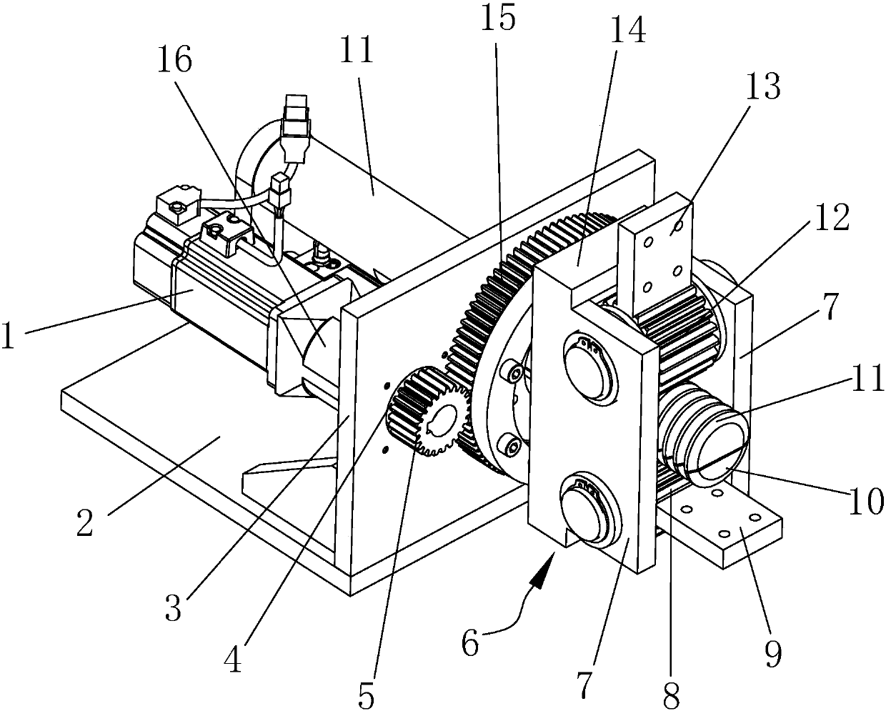
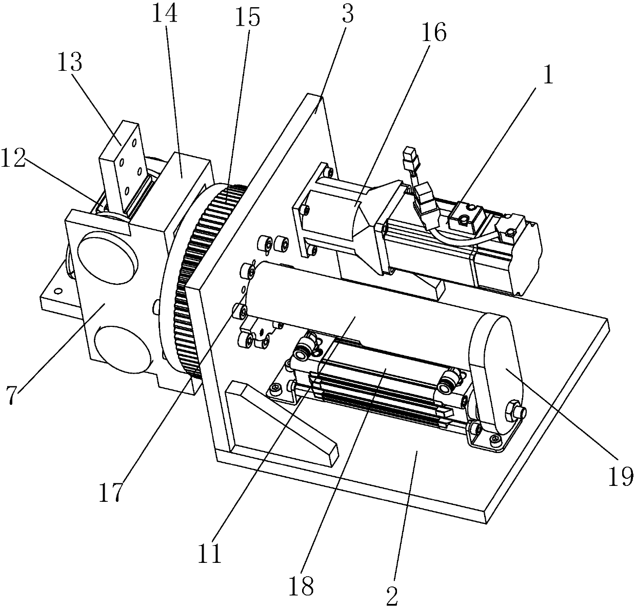
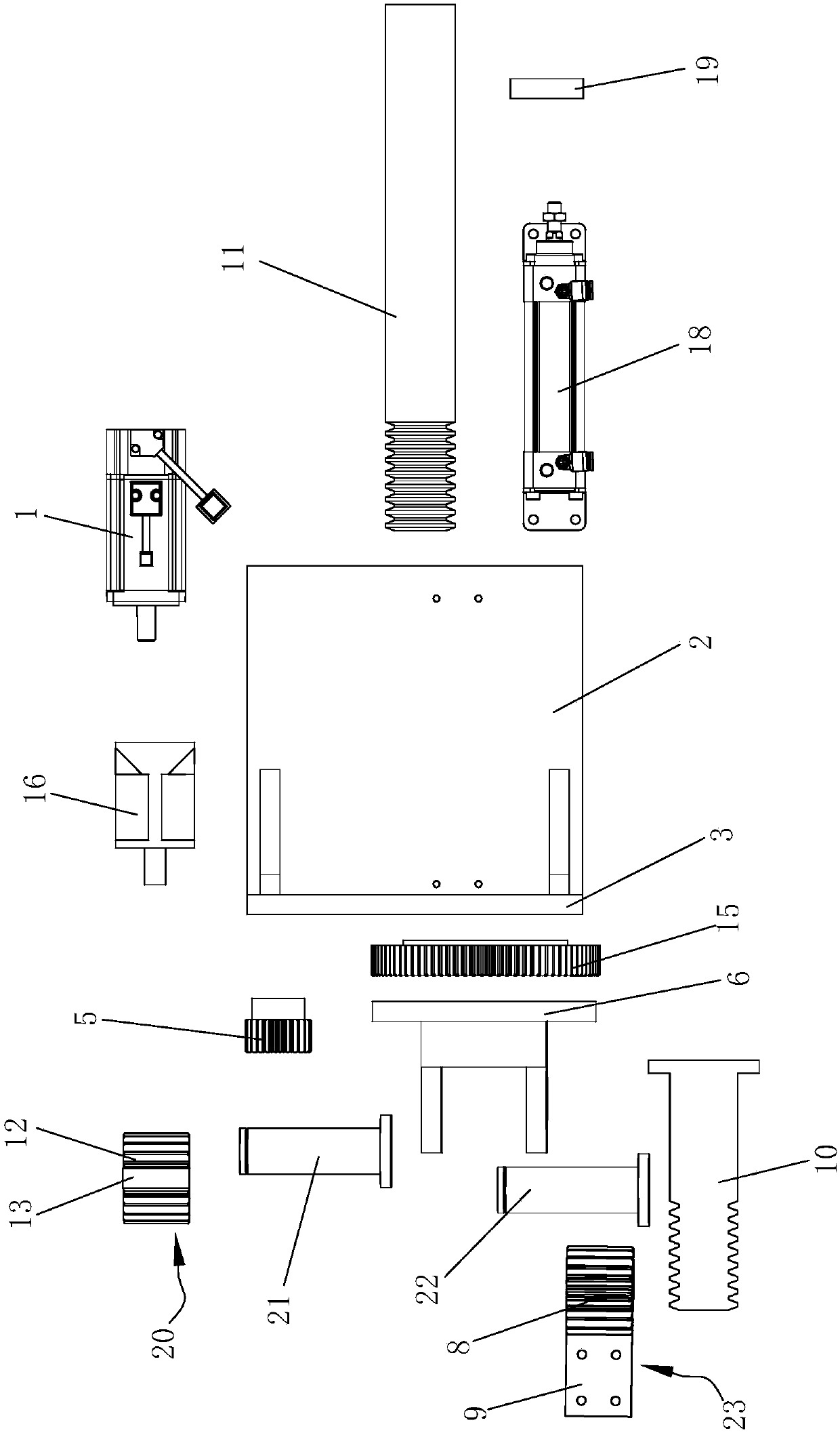
[0015] Such as Figure 1 to Figure 3 As shown, the servo turning machine of the present invention includes a mounting table, a motor 1, a reducer 16, a cylinder 18, a pinion 5, a large gear 15, a base 6, a platen gear I23, a platen gear II20, a half cylindrical rack I11, a half Cylindrical rack II 10.

[0016] Described mounting table comprises horizontal mounting plate 2 and the vertical mounting plate 3 that is vertically connected at one end of horizontal mounting plate 2, and speed reducer 16 is connected to the output end of motor 1 and is positioned on the surface of vertical mounting plate 3 side, with The vertical mounting plate 3 corresponding to the reducer 16 is also provided with a through hole I4 for the output shaft of the reducer 16 to pass through, the pinion gear 5 is connected to the output shaft of the reducer 16 passing through the through hole I4, and the large gear 15 is positioned On the vertical mounting plate 3 and on one side of the pinion 5, and the...


PUM


Abstract

The invention relates to a turnover mechanism used in a production line, in particular to a servo turnover machine. The servo turnover machine comprises an installation table, a motor, a speed reducer, an air cylinder, a pinion, a big gear, a base, a pressing plate gear I, a pressing plate gear II, a half-cylinder rack I and a half-cylinder rack II. The pinion is a straight gear, the big gear is a toothed crossed roller bearing, the base fixed to the crossed roller bearing is driven through the rotating and meshing motion of the straight gear and the toothed crossed roller bearing, and therefore plates can rotate. When the plates need to be turned over, the air cylinder extends out, the half-cylinder rack I fixedly connected to a telescopic shaft of the air cylinder is pulled, the pressing plate gear I meshing with the half-cylinder rack I does rotating and clamping motion, and therefore the plates to be turned over can be clamped. When a system detects that the plates are clamped, the motor is driven to rotate to the position where the plates are to be turned over, the system then controls the air cylinder to retract, the pressing plate gear I meshing with the half-cylinder rack I does rotating and opening motion, and therefore the plates can be turned over.

Description

technical field [0001] The invention relates to a turning mechanism used in a production line, in particular to a servo turning machine. Background technique [0002] In an automatic production line, in order to realize automatic production, some turning equipment is often needed to turn over the workpiece. Most of the turning equipment currently on the market can only rotate at a fixed angle, and the applicability is relatively low. When the turning equipment clamps the workpiece, the positioning accuracy is not accurate enough, the turning speed is slow, and the automatic turning mechanism rarely appears on the automatic production line of small stamping. , When small pieces of stamping sheets need to be turned over, the sheets are usually turned over manually, which has a low degree of automation and low production efficiency. Contents of the invention [0003] The purpose of the present invention is to provide a servo turning machine, which can be used in the stamping...

Claims


Application Information

Patent Timeline
Patent Type & Authority Patents(China)
IPC IPC(8): B21D43/14B21D43/00
CPCB21D43/003B21D43/145
Inventor 黄连勇
Owner LIUZHOU GAOHUA TECH CO LTD
Why Eureka
Try Eureka