A bolt fastening machine

A fastening machine and bolt technology, applied in metal processing, metal processing equipment, manufacturing tools, etc., can solve problems such as low labor efficiency, increased equipment cost, and inaccurate manual methods, so as to reduce the number of wrenches and equipment costs , the effect of high fixed precision

Active Publication Date: 2018-03-20
山东中际钇嘉智能装备有限公司
View PDF8 Cites 0 Cited by
  • Summary
  • Abstract
  • Description
  • Claims
  • Application Information

AI Technical Summary

Problems solved by technology

At present, many bolts are tightened manually or mechanically. The manual tightening method requires one-to-one tightening of manpower, which results in uneven tightening accuracy and strength of the bolts, resulting in poor sealing of the front cover of the compressor. Equipment with strict technical parameters, the manual method is not accurate, it is difficult to judge whether the bolts are fixed in place based on experience alone, and the labor efficiency of the manual method is too low, and the balance force between the bolts is not well grasped
For the mechanical tightening method, multiple wrenches are fully automatic to tighten the bolts at the same time, which can achieve precise control, but in the case of too many bolts, each bolt needs to be equipped with a wrench, which will increase the cost of the equipment. If there are too many, the space for fixing the wrench is insufficient, and the coupling needs to be added, so more power loss will be caused, and the equipment structure and supporting facilities will be more complicated

Method used


Image

  • A bolt fastening machine
  • A bolt fastening machine
  • A bolt fastening machine

Examples


Embodiment 1

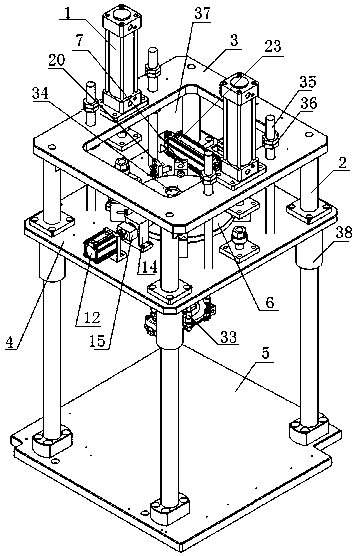
[0034] In this embodiment, the application of the bolt tightening machine is explained by taking the bolts on the front cover of the automobile compressor as an example. In this embodiment, the number of bolts is set to an even number, and the number of corresponding electric wrenches is the number of bolts. The distance between adjacent electric wrenches is an integer multiple of the adjacent bolts.

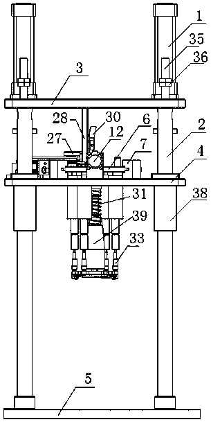
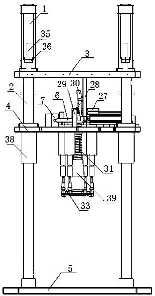
[0035] The bolt tightening machine of this embodiment includes a power system, a guide column 2, a fixed platform 3, a lifting plate 4, a bearing platform 5, and a fastening device; wherein, the lifting plate 4 is located between the fixed platform 3 and the bearing platform 5. The fixed platform 3, the lifting plate 4, and the bearing platform 5 are in the same vertical space. The middle of the fixed platform 3 and the lifting plate 4 is provided with an opening 37 for the fastening device to move up and down. The position of the opening 37 is for the fastening device to move up an...


PUM


Abstract

The invention relates to the field of mechanical equipment, in particular to a bolt fastening machine. The bolt fastening machine comprises a lifting plate and a fastening device positioned on the lifting plate, wherein the middle part of the lifting plate is provided with an opening for allowing the fastening device to move up and down; the fastening device comprises a tray which is positioned in a middle opening of the lifting plate, a floating mechanism which penetrates through the tray, a plurality of dowel pins positioned on the upper surface of the tray, a plurality of rotary positioning mechanisms which are positioned on the upper surface of the lifting plate and are arranged at the periphery of a circular opening, a locking device which is positioned on the upper surface of the lifting plate and is matched with the plurality of the dowel pins for use, and a rotary pushing mechanism which is positioned on the upper surface of the lifting plate and is connected to the side surface of the tray; the tray is embedded into an area which is defined by the plurality of the rotary positioning mechanisms and the locking device; the tray is circular; and the plurality of the rotary positioning mechanisms are distributed at equal spacing at the periphery of the tray. The bolt fastening machine can realize precise control on a bolt while reducing number of wrenches, so that tightness of a mechanical device is ensured.

Description

Technical field [0001] The invention relates to the field of mechanical equipment, in particular to a bolt tightening machine. Background technique [0002] Most of the existing machinery and equipment are equipped with bolts, and the bolts are distributed in many positions. In order to facilitate the connection of different parts to form a whole mechanical equipment, the number of bolts used is relatively large. For example, the bolts on the front cover of the compressor are located on the same plane and arranged in an even number to fasten the compressor. At present, many bolts are tightened manually or mechanically. The manual tightening method requires one-to-one tightening by manpower. As a result, the tightening accuracy and strength of the bolts are not balanced, resulting in poor sealing of the compressor front cover. For equipment with strict technical parameters, the manual method is not accurate. It is difficult to judge whether the bolts are fixed in place from exper...

Claims


Application Information

Patent Timeline
Patent Type & Authority Patents(China)
IPC IPC(8): B23P19/06
CPCB23P19/069
Inventor 王世林
Owner 山东中际钇嘉智能装备有限公司
Why Eureka
Try Eureka