
Automatic cutter sharpening device

A technology for automatic knife sharpening and sheet grinding, which is applied to grinding drive devices, grinding machines, grinding racks, etc., and can solve the problems of unbalanced tool force, tool offset, and affecting the grinding effect, and achieves a high degree of automation. Precise and reliable action, good grinding effect

Active Publication Date: 2016-09-28
黄小良 +1
View PDF6 Cites 5 Cited by
  • Summary
  • Abstract
  • Description
  • Claims
  • Application Information

AI Technical Summary

Problems solved by technology

[0004] Due to the staggered arrangement of the two grinding wheels in the knife sharpening device disclosed in the above-mentioned patent documents, when the knife is sharpened, the force on both sides of the knife is unbalanced, which easily causes the knife to shift and affects the grinding effect. Using two driving motors to drive separately, it is difficult to ensure the synchronization and consistency of the rotation of the two grinding wheels, thus affecting the balance of the grinding effect on both sides of the tool; in addition, there is no automatic feeding and clamping structure of the tool in this technical solution, which affects Sharpening efficiency

Method used


Image

  • Automatic cutter sharpening device
  • Automatic cutter sharpening device
  • Automatic cutter sharpening device

Examples


Embodiment Construction

[0026] The following are specific embodiments of the present invention and in conjunction with the accompanying drawings, the technical solutions of the present invention are further described, but the present invention is not limited to these embodiments.

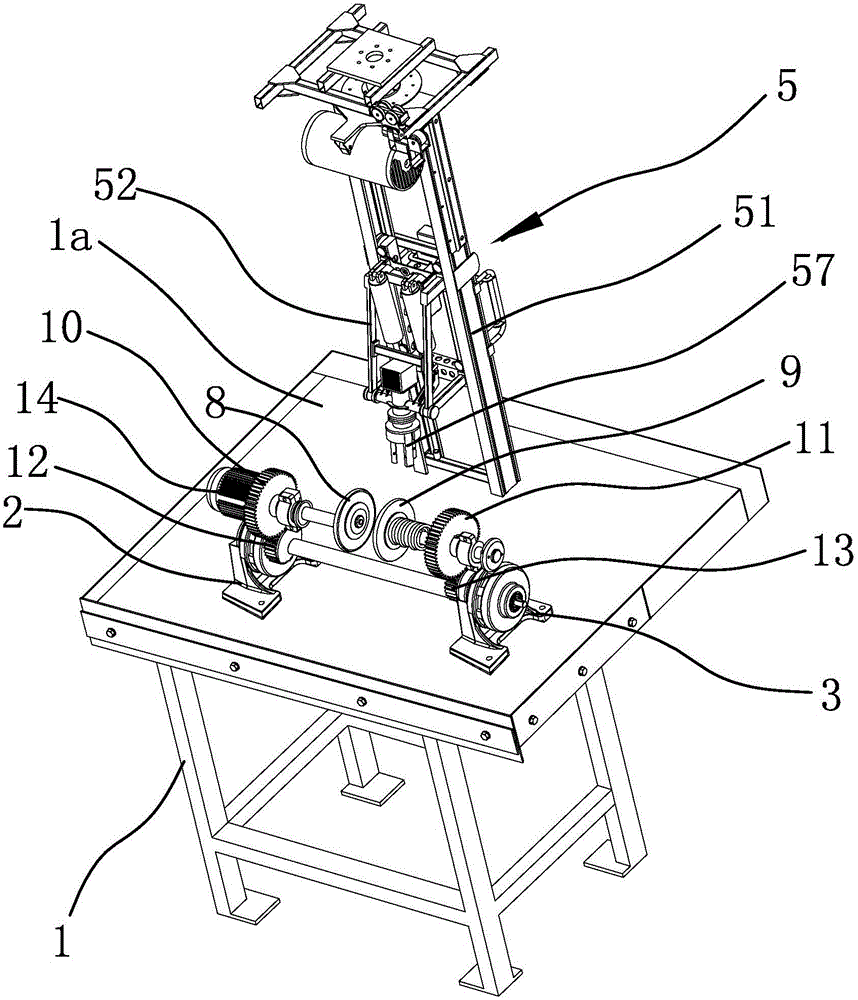
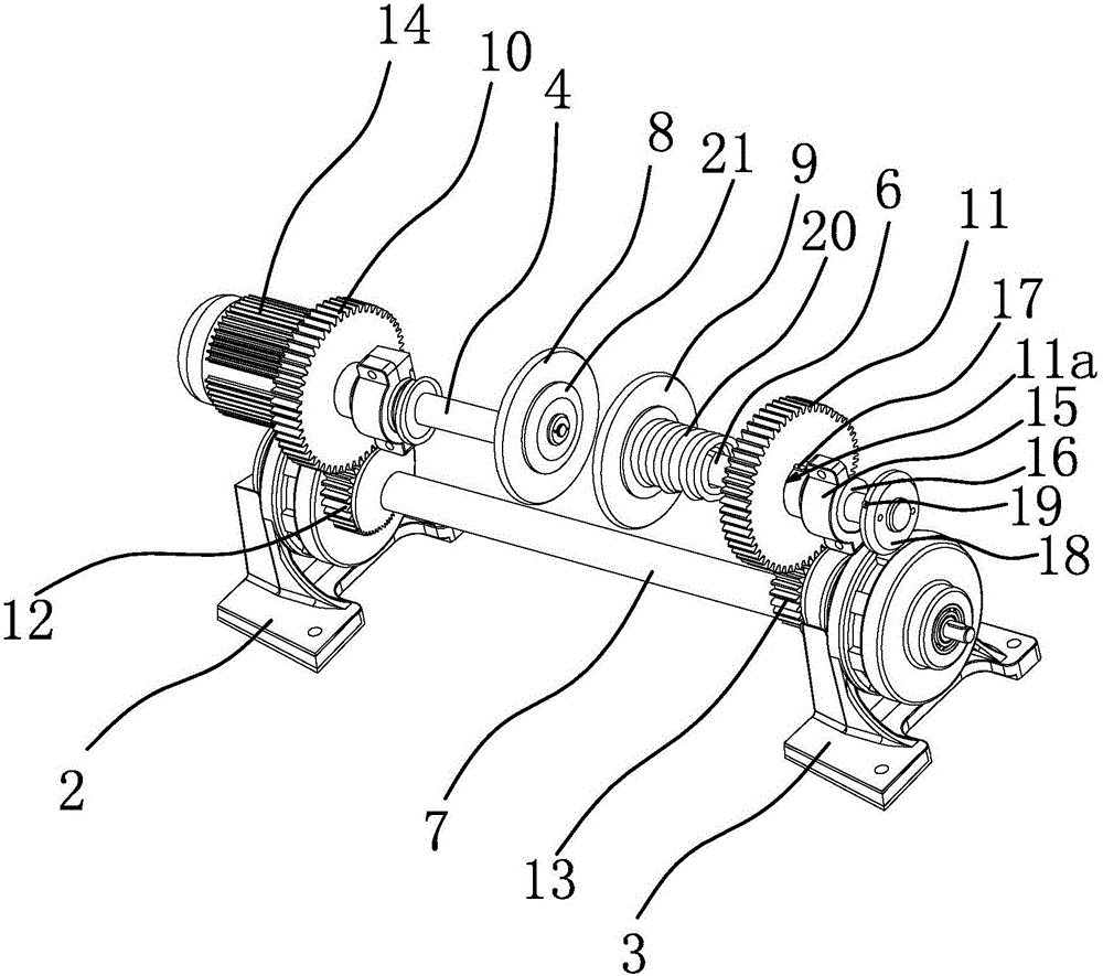
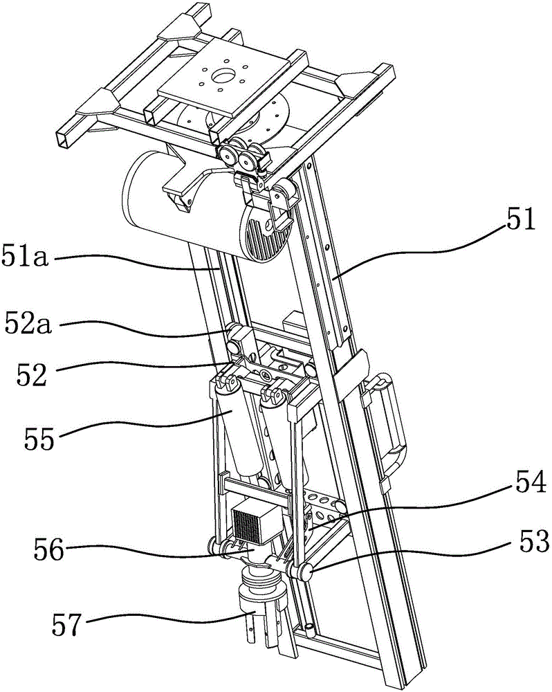
[0027] Such as figure 1 and figure 2As shown, the automatic knife sharpening device includes a base 1, the base 1 has a mounting platform 1a, the mounting base 1 2 and the mounting base 2 3 are relatively fixed at intervals on the mounting platform 1a, and the mounting base 2 is provided with a rotatable driving shaft 4 and the motor 14 that can drive the driving shaft 4 to rotate, the mounting seat 2 3 is provided with a driven shaft 6 that can rotate; The end of the driven shaft 6 is fixed with a grinding wheel 2 9; the driven shaft 6 is also circumferentially fixed with a gear 2 11; a rotatable transmission shaft is also provided between the mounting seat 2 and the mounting seat 2 3 7. The two ends of the transmissio...


PUM


Abstract

The invention provides an automatic cutter sharpening device, belongs to the technical field of mechanical devices, and solves such technical problems as low efficiency and weak effect in a traditional automatic cutter sharpening device. The automatic cutter sharpening device comprises a mounting base I and a mounting base II oppositely fixedly arranged in a spaced manner; the mounting base I is provided with a driving shaft capable of rotating and a motor capable of driving the driving shaft to rotate; the mounting base II is provided with a driven shaft capable of rotating; a grinding wheel I is arranged at the end part of the driving shaft; a gear I is fixedly arranged on the driving shaft; a grinding wheel II is fixedly arranged at the end part of the driven shaft; a gear II is peripherally fixedly arranged on the driven shaft; a transmission shaft capable of rotating is arranged between the mounting base I and the mounting base II; a gear III and a gear IV are respectively fixedly arranged at two ends of the transmission shaft; the gear I is engaged with the gear III; and the gear II is engaged with the gear IV. The grinding wheel I and the grinding wheel II are synchronously driven to rotate by one motor, are consistent and unified in grinding of two sides of a cutter, and are balanced and uniform to further improve the effect.

Description

technical field [0001] The invention belongs to the technical field of mechanical devices and relates to an automatic sharpening device. Background technique [0002] Knife is a tool commonly used in daily life. If it is used for a long time, the edge of the knife will become blunt, which will affect the use. It is wasteful to replace the new knife because the edge becomes blunt. After sharpening it, it will become sharp, thus Can be reused. In real life, people usually use whetstones for manual sharpening, which is inefficient and time-consuming; with the progress of production and life, it becomes very impractical to use manual sharpening when a large number of knives are needed; therefore, people invented Electric knife sharpening device; due to structural limitations, most of the existing knife sharpening devices need to be manually adjusted to sharpen both sides of the blade, which is inconvenient and unsafe to use, and the grinding speed is slow and the grinding effec...

Claims


Application Information

Patent Timeline
Patent Type & Authority Applications(China)
IPC IPC(8): B24B3/00B24B27/00B24B41/02B24B41/00B24B47/08B24B47/12
CPCB24B3/00B24B27/0076B24B41/005B24B41/007B24B41/02B24B47/08B24B47/12
Inventor 黄小良
Owner 黄小良
Learn More