Flow regulating valve

A technology of flow regulating valve and valve core, which is applied in the direction of sliding valve, valve device, engine components, etc., to achieve the effect of simple structure and precise flow control

Active Publication Date: 2016-09-28
FOSHAN VIOMI ELECTRICAL TECH +1
View PDF7 Cites 2 Cited by
  • Summary
  • Abstract
  • Description
  • Claims
  • Application Information

AI Technical Summary

Problems solved by technology

[0005] The flow regulating valve includes a valve body and a spool driving mechanism. The valve body is provided with a water inlet pipeline, a water outlet pipeline, and a valve core assembly connecting the water inlet pipeline and the water outlet pipeline. It is characterized in that the valve core assembly includes the first A spool and a second spool, the first spool is provided with an opening, the second spool is provided with a water hole, the water hole includes at least two sections of the water hole section that communicate with each other, and the adjacent two The sizes of the water hole sections are not equal, the opening of the first spool and the water hole of the second spool communicate with the corresponding water inlet pipeline and water outlet pipeline respectively, and the openings on the first spool and the second spool and the surface where the water hole is located, the spool driving mechanism drives the first spool or the second spool to rotate, so that the overlapping area between the opening of the first spool and the water hole of the second spool forms a communication The water flow control channel of the water inlet pipe and the water outlet pipe; this type of flow regulating valve, by setting the water hole on one of the valve cores to include at least two water hole sections that communicate with each other, the adjacent two The size of the water hole section is different. At this time, when the other valve core rotates, its opening can ensure the same overlapping interval with the same water hole section, that is, the water flow control channel has the same size to realize the water flow control. The water flow in the channel is consistent, so even if the regulating valve uses different spool drive mechanisms, such as: different motors, in the same water hole section on the water hole, the same flow can be obtained, that is, the motor can be controlled to rotate and Drive the opening on the other spool to rotate to the center of each water hole section, even if there is a deviation in the left and right angles, a consistent flow value can be obtained to overcome the difference in the selected motor or the assembly of the motor and the motor shaft error, resulting in inaccurate flow control, and the whole structure is simple and reasonable

Method used


Image

  • Flow regulating valve
  • Flow regulating valve
  • Flow regulating valve

Examples


Embodiment Construction

[0026] The present invention will be further described below in conjunction with accompanying drawing and embodiment:

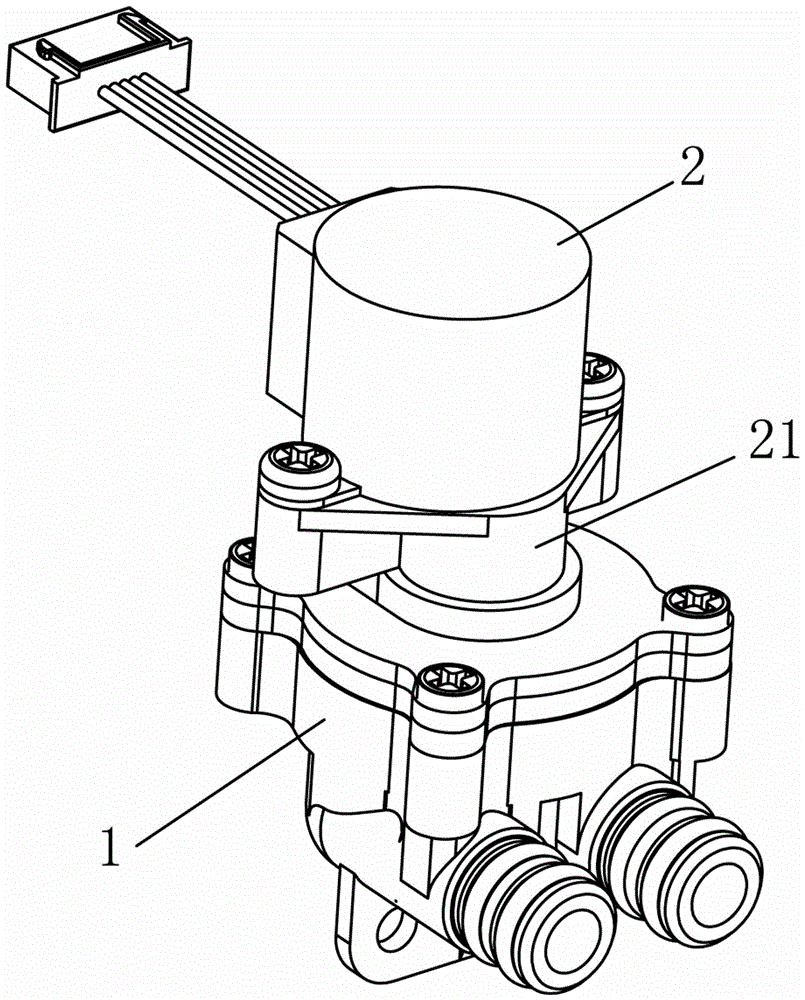
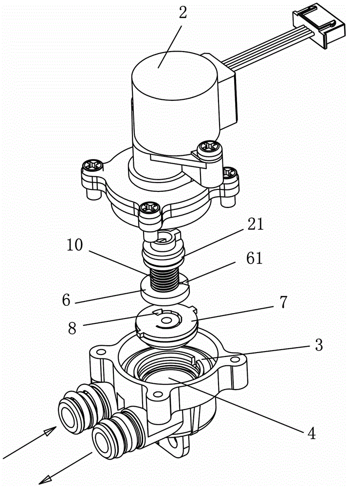
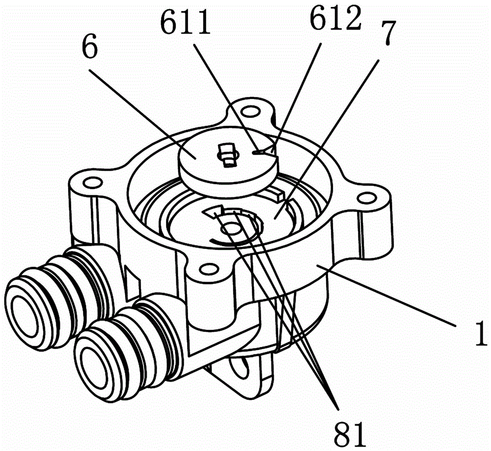
[0027] See Figure 1 to Figure 7 As shown, a flow regulating valve includes a valve body 1 and a valve core driving mechanism 2, the valve core driving mechanism 2 is a stepping motor, and the valve body 1 is provided with a water inlet pipeline 3, a water outlet pipeline 4 and a water inlet pipeline 3 and the spool assembly 5 of the water outlet pipeline 4, characterized in that the spool assembly 5 includes a first spool 6 and a second spool 7, the first spool 6 is provided with an opening 61, and the second spool 7 is provided with a water passage hole 8, the water passage hole 8 includes at least two sections of water passage hole sections 81 that communicate with each other, the sizes of the two adjacent water passage hole sections 81 are different, and the opening 61 of the first valve core It communicates with the corresponding water inlet pipeline 3 ...


PUM


Abstract

The invention discloses a flow regulating valve which comprises a valve body and a valve element driving mechanism. A water inlet pipeline, a water outlet pipeline and a valve element assembly connected with the water inlet pipeline and the water outlet pipeline are arranged on the valve body. The flow regulating valve is characterized in that the valve element assembly comprises a first valve element and a second valve element. An opening is formed in the first valve element, and a water through hole is formed in the second valve element. The water through hole comprises at least two water through hole sections communicating with one another. Every two adjacent water through hole sections are different in size. The opening of the first valve element and the water through hole of the second valve element communicate with the water inlet pipe and the water outlet pipe correspondingly. The face, with the opening, of the first valve element is attached to the face, with the water through hole, of the second valve element. The valve element driving mechanism drives the first valve element or the second valve element to rotate so that an overlapped interval between the opening of the first valve element and the water through hole of the second valve element forms a water flow control channel communicating with the water inlet pipe and the water outlet pipe. The flow regulating valve has the advantages that flow control is accurate, and the overall structure is simple and reasonable.

Description

technical field [0001] The invention relates to a flow regulating valve, in particular to a flow regulating valve which can improve the accuracy of water flow control. Background technique [0002] The existing flow regulating valve includes a valve body and a spool driving mechanism. The valve body is provided with a water inlet pipeline, a water outlet pipeline and a valve core assembly connecting the water inlet pipeline and the water outlet pipeline. The valve core driving mechanism drives the valve core to move , in order to realize the water flow adjustment of the water inlet pipeline and the water outlet pipeline; among them, the spool drive mechanism uses a stepping motor to control the flow, however, due to the certain error between the motor and the motor shaft, there will be differences between different products There is a large error, especially when the input water pressure is relatively large, the difference in the flow of different water flow control channels...

Claims


Application Information

Patent Timeline
Patent Type & Authority Applications(China)
IPC IPC(8): F16K3/312F16K3/34
CPCF16K3/312F16K3/34
Inventor 陈小平
Owner FOSHAN VIOMI ELECTRICAL TECH
Why Eureka
Try Eureka