
A Tunable Self-Calibrating Optical Gyroscope Based on Surface Plasmon Waveguide

A surface plasmon and optical gyroscope technology, applied in the field of integrated optical and inertial sensors, can solve the problems of insufficient competitiveness of high-precision optical gyroscopes, difficult to achieve high-precision navigation products, and optical gyroscope accuracy limitations, and achieve stability and reliability. The effect of improving, improving dynamic range, reducing polarization noise

Active Publication Date: 2018-08-21
SOUTHEAST UNIV
View PDF5 Cites 0 Cited by
  • Summary
  • Abstract
  • Description
  • Claims
  • Application Information

AI Technical Summary

Problems solved by technology

Due to the existence of polarization errors, the accuracy of optical gyroscopes in current applications is difficult to achieve the application of high-precision navigation products. Therefore, the development of optical gyroscopes that can eliminate polarization errors is the key to the development of optical gyroscopes.
[0003] Traditional optical gyroscopes use polarization-maintaining fibers or depolarizers to reduce polarization errors. However, when optical gyroscopes work for a long time, the parasitic birefringence of optical components such as couplers and Y-waveguide integrated chips in the optical path or internal defects in materials will still affect the optical path. Bringing non-reciprocity, resulting in polarization crosstalk or polarization cross-coupling, resulting in the accumulation of polarization errors over time, the accuracy of the optical gyroscope is limited, and the cost of polarization-maintaining fiber is too high, so the competitiveness of high-precision optical gyroscopes Insufficient, even the application in low-to-medium precision navigation systems is also restricted

Method used


Image

  • A Tunable Self-Calibrating Optical Gyroscope Based on Surface Plasmon Waveguide
  • A Tunable Self-Calibrating Optical Gyroscope Based on Surface Plasmon Waveguide
  • A Tunable Self-Calibrating Optical Gyroscope Based on Surface Plasmon Waveguide

Examples


Embodiment Construction

[0022] The technical scheme of the present invention is described in detail below in conjunction with accompanying drawing:

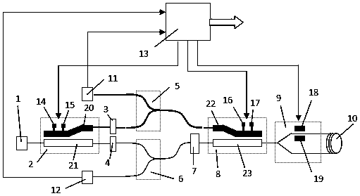
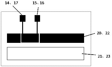
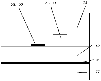
[0023] A tunable self-calibrating optical gyroscope based on a surface plasmon waveguide proposed by the present invention, from a structural point of view, the optical gyroscope consists of a light source 1 and a tunable surface plasmon mode separator 2 in sequence from the input end to the output end , optical isolator one 3, optical isolator two 4, surface plasmon coupler 5, Y branch coupler 6, polarizer 7, tunable surface plasmon mode separator 8, Y waveguide integrated optical gyro chip 9 , a single-mode fiber coil 10, a photodetector 11, a photodetector 2 12, and a phase compensation feedback unit 13; the positional relationship is that the output of the light source 1 is connected to the input of the tunable surface plasmon mode separator 2, and there are metal strips The output terminal of the surface plasmon waveguide arm 20 of the structure is...


PUM


Abstract

The invention provides a tunable self-calibration optical gyro based on surface plasmon polariton waveguide. The optical gyro comprises the following components: a light source, a tunable surface plasmon polariton mode splitter, an isolator, a surface plasmon polariton coupler, a Y-branch coupler, a polarizer, a single-mode fiber coil, a detector and phase compensation feedback unit. The inveniton belongs to the field of inertial sensing technology and integrated optics field, and the tunable self-calibration optical gyro based on surface plasmon polariton waveguide is provided, the tunable surface plasmon polariton mode splitter is used in order to realize mode separation and phase compensation of light signals of different polarization states, and the tunable self-calibration optical gyro is realized and has the advantages of low noise, low cost, high precision, wide dynamic range, high stability, and high light source utilization rate.

Description

technical field [0001] The invention belongs to the technical field of integrated optics and inertial sensors, in particular to a tunable self-calibrating optical gyroscope based on surface plasmon waveguides. Background technique [0002] Gyroscope is an important measurement element of inertial navigation system and inertial guidance system, and is the core of the entire inertial system. Its measurement accuracy directly affects the performance of inertial navigation system and inertial guidance system. With the development of inertial technology, various types of gyroscopes have appeared one after another, such as electromechanical gyroscopes such as liquid floating gyroscopes, flexible gyroscopes, electrostatic gyroscopes, and piezoelectric gyroscopes. The optical gyroscope is a new type of photoelectric gyroscope based on the Sagnac effect. The development of its technology benefits from the progress of laser technology and optical communication technology. The emergen...

Claims


Application Information

Patent Timeline
Patent Type & Authority Patents(China)
IPC IPC(8): G01C19/72
CPCG01C19/72
Inventor 张彤唐杰张晓阳
Owner SOUTHEAST UNIV
Learn More