
Blocking mechanism simulation force measuring apparatus

The technology of a force measuring device and a locking mechanism is applied in the direction of measuring devices, force/torque/work measuring instruments, instruments, etc., which can solve the problems such as the inability to realize the locking mechanism and the need for locking force testing, and achieves strong operability and simple production. , The effect of high force measurement accuracy

Active Publication Date: 2016-09-28
HUBEI SANJIANG AEROSPACE WANFENG TECH DEV
View PDF3 Cites 5 Cited by
  • Summary
  • Abstract
  • Description
  • Claims
  • Application Information

AI Technical Summary

Problems solved by technology

[0003] At present, the testing requirements for the locking force of the locking mechanism cannot be realized in the existing technology, and there is no experience for reference

Method used


Image

  • Blocking mechanism simulation force measuring apparatus
  • Blocking mechanism simulation force measuring apparatus
  • Blocking mechanism simulation force measuring apparatus

Examples


Embodiment Construction

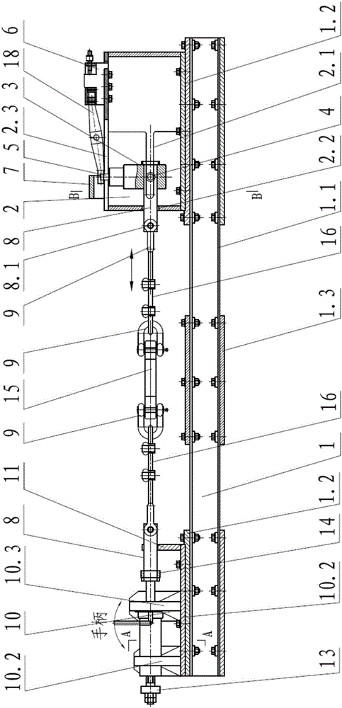
[0034] In order to make the object, technical solution and advantages of the present invention clearer, the present invention will be further described in detail below in conjunction with the accompanying drawings and embodiments. It should be understood that the specific embodiments described here are only used to explain the present invention, not to limit the present invention. In addition, the technical features involved in the various embodiments of the present invention described below can be combined with each other as long as they do not constitute a conflict with each other.

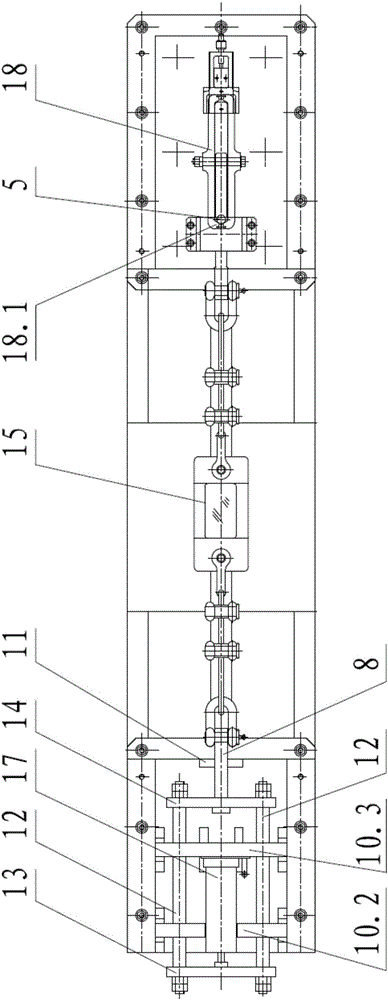
[0035] figure 1 ~ Fig. 5 is an embodiment of the present invention. The front, back, left, right, up, and down positions in this embodiment, unless otherwise specified, are all represented by figure 1 Based on the orientation in the figure 1 In, the front and back refer to the vertical figure 1 Orientation on paper, correspondingly, due to figure 2 yes figure 1 top view of figure 1 The f...


PUM


Abstract

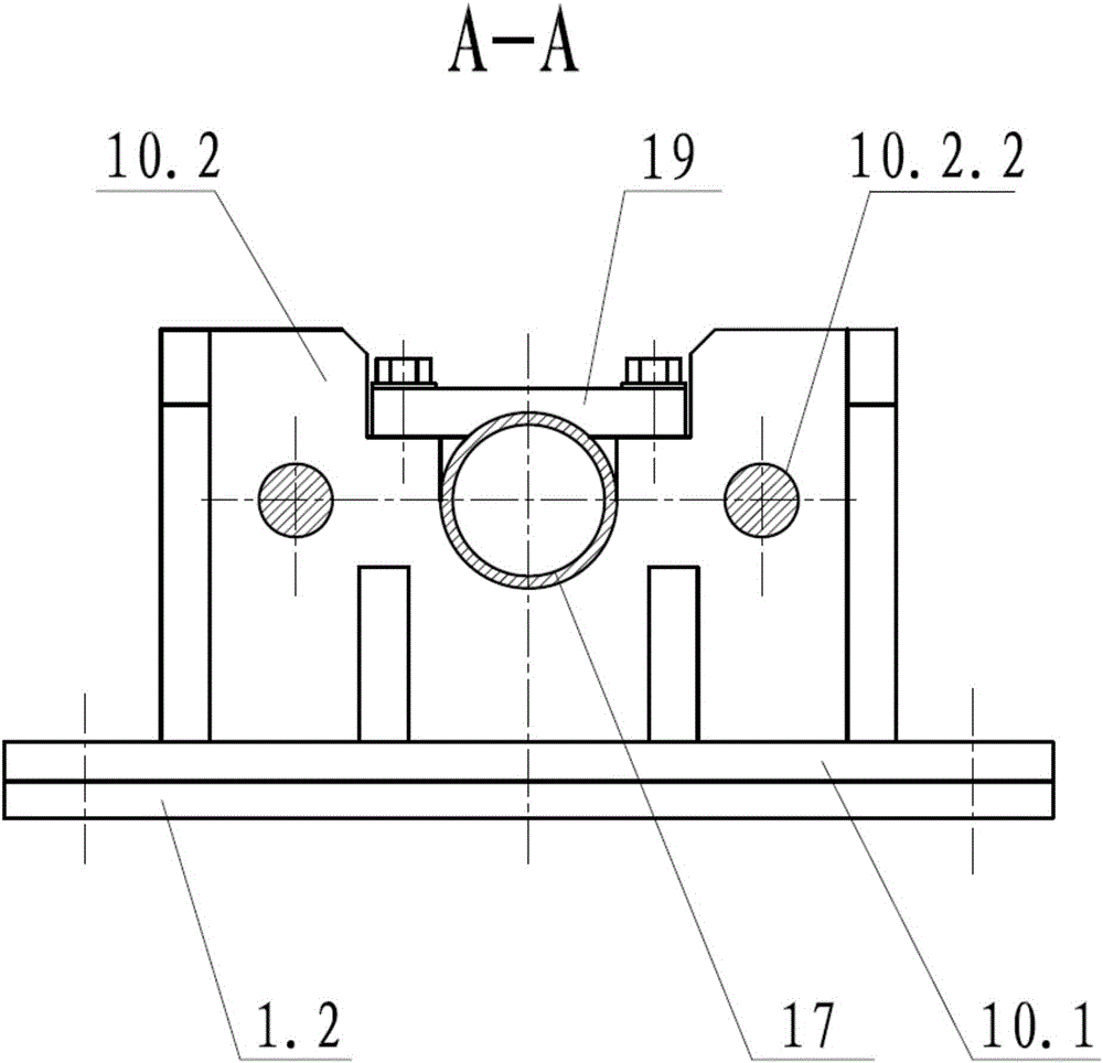
The invention discloses a blocking mechanism simulation force measuring apparatus which includes a pedestal which includes three channel steels; right ends of the three channel steels are provided with a case body assembly which is provided with a force measuring support therein; the force measuring support is provided with a force measuring pin on the left side of an upper end thereof, and the case body assembly is provided with a fixing seat on the right side of an upper plane, and the force measuring pin and the fixing seat are intended for fixing a to-be-tested product during tests; left ends of the three channel steels are provided with a support assembly which is provided with two guide rods thereon which are parallel to each other, and one ends of the guide rods are provided with a top plate and the other ends of the guide rods are provided with an installing plate; two semi-arc pulling force shafts are oppositely arranged with one arranged on the force measuring support and the other arranged on the support assembly; a digital display force measuring device with two ends are in respective connection to the two semi-arc pulling force shafts; and a hydraulic jack is installed in the support assembly. According to the invention, the apparatus can meet demands for testing the opening and closing force of the blocking mechanism. The apparatus is characterized by reliable positioning, high structural strength, small deformation, easy mounting and dismounting, easy carrying, and repeatable usage.

Description

technical field [0001] The invention belongs to the field of locking force testing, and more particularly relates to a locking mechanism simulation force measuring device. Background technique [0002] The locking mechanism can be used for locking ejected objects in confined spaces, and such ejected objects can be used for high-altitude detection, building fire extinguishing, etc. The locking mechanism has two functions, one is to clamp the guide pin in the transportation state to limit the forward movement of the projectile, and the other is to move forward after overcoming the locking force when the projectile is launched; the locking force of the locking mechanism directly affects whether the projectile can It is launched smoothly, and whether the projectile is stable and reliable when it is installed in the launch tube and travels with the launch vehicle. Before the locking mechanism is used, a reliability simulation test is required, that is, the locking mechanism simu...

Claims


Application Information

Patent Timeline
Patent Type & Authority Applications(China)
IPC IPC(8): G01L5/00
CPCG01L5/0033
Inventor 邓平盛孔令辉刘卫星龙登坛王元成代洪雷
Owner HUBEI SANJIANG AEROSPACE WANFENG TECH DEV
Learn More