
Clamping tool for antenna test and test method

A technology for antennas and fixtures, applied in fixtures for antenna testing and in the field of testing, can solve the problems of wasting qualified products, outflowing unqualified products, and decreasing the stability of antenna test fixtures, so as to avoid testing and judgment errors and improve detection accuracy Effect

Inactive Publication Date: 2016-09-28
SHENZHEN SUNWAY COMM
View PDF9 Cites 1 Cited by
  • Summary
  • Abstract
  • Description
  • Claims
  • Application Information

AI Technical Summary

Problems solved by technology

[0003] The technical problem to be solved by the present invention is: the phenomenon of wasting qualified products and flowing out of unqualified products due to the decrease in the stability of the antenna test fixture

Method used


Image

  • Clamping tool for antenna test and test method
  • Clamping tool for antenna test and test method
  • Clamping tool for antenna test and test method

Examples


Embodiment Construction

[0023] In order to describe the technical content, achieved goals and effects of the present invention in detail, the following descriptions will be made in conjunction with the embodiments and accompanying drawings.

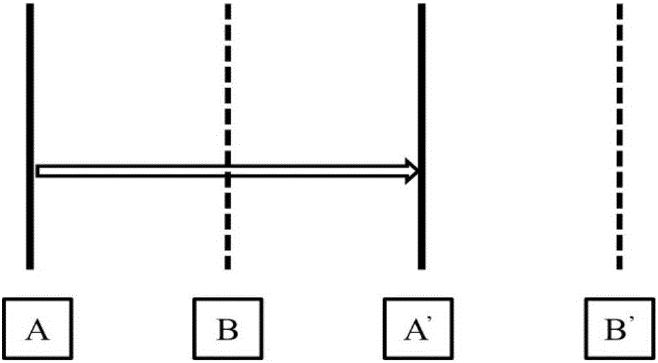
[0024] The most critical idea of ​​the present invention is: the antenna test fixture is provided with at least two electrical performance detection main boards and at least two sets of fixing devices. This design allows the testing of the limit sample and the sample to be tested to be carried out simultaneously, and the test can be performed in the same state. The obtained threshold value is used to determine whether the sample to be tested is qualified or not, which avoids the test and judgment errors caused by the stability fluctuation of the test fixture itself, and improves the detection accuracy.

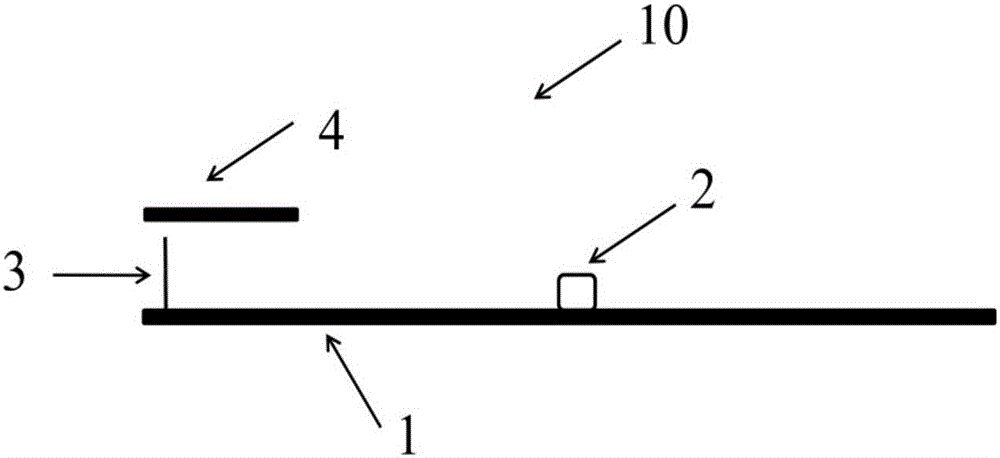
[0025] Please refer to figure 2 and image 3 , a fixture for antenna testing, including a base body, a pressing device, and at least two main boards for elect...


PUM


Abstract

The invention provides a clamping tool for an antenna test and a test method. The clamping tool comprises a seat body, a pressing device and at least two electric performance detection main boards and at least two sets of fixing devices. The design of the clamping tool enables tests for limit samples and samples to be tested to be performed synchronously. A threshold value obtained through testing the limit samples under a same state can be used for determining whether the sample to be tested is qualified or not. The clamping tool and the test method reduce the test and determination errors which are caused by fluctuation in stability of the test clamping tool to the maximum, and improve detection precision.

Description

technical field [0001] The invention relates to the field of communication equipment, in particular to a jig for antenna testing and a testing method. Background technique [0002] At present, antenna manufacturers will use the electrical performance full inspection scheme to test the electrical performance of the product when the product is inspected at the factory. Specifically, the antenna test fixture is designed according to the product's shape, circuit form, performance and other factors. The fixture is connected to the test instrument, and then the product to be tested is placed on the test fixture. After the fixture fixes the product to be tested, the test can be started. Before the test, a limit product is tested, and its test parameters are used as the test threshold. During the test, the test instrument is connected to the control computer, the threshold value in the control computer is set, and the test result is compared with the threshold value to determine wh...

Claims


Application Information

Patent Timeline
Patent Type & Authority Applications(China)
IPC IPC(8): G01R29/10G01R1/04
CPCG01R29/10G01R1/0408
Inventor 毕晔海
Owner SHENZHEN SUNWAY COMM
Learn More