
PTZ structure and camera module

A camera module and gimbal technology, applied in the field of flight control, can solve the problems of resource waste, gimbal structure and camera module cannot be separated from each other, and achieve the effect of high combination freedom

Active Publication Date: 2021-10-08
BEIJING XIAOMI MOBILE SOFTWARE CO LTD +1
View PDF6 Cites 0 Cited by
  • Summary
  • Abstract
  • Description
  • Claims
  • Application Information

AI Technical Summary

Problems solved by technology

Of course, the camera module itself can actually be applied to general shooting scenes in daily life or work, but because the pan-tilt structure and the camera module in the related art are integrated, that is, there is no connection between the pan-tilt structure and the camera module. Separated from each other, due to the consideration of carrying, use, etc., it can only be used in conjunction with the aircraft as a whole, resulting in a waste of resources

Method used


Image

  • PTZ structure and camera module
  • PTZ structure and camera module
  • PTZ structure and camera module

Examples


Embodiment Construction

[0033] Reference will now be made in detail to the exemplary embodiments, examples of which are illustrated in the accompanying drawings. When the following description refers to the accompanying drawings, the same numerals in different drawings refer to the same or similar elements unless otherwise indicated. The implementations described in the following exemplary examples do not represent all implementations consistent with the present disclosure. Rather, they are merely examples of apparatuses and methods consistent with aspects of the present disclosure as recited in the appended claims.

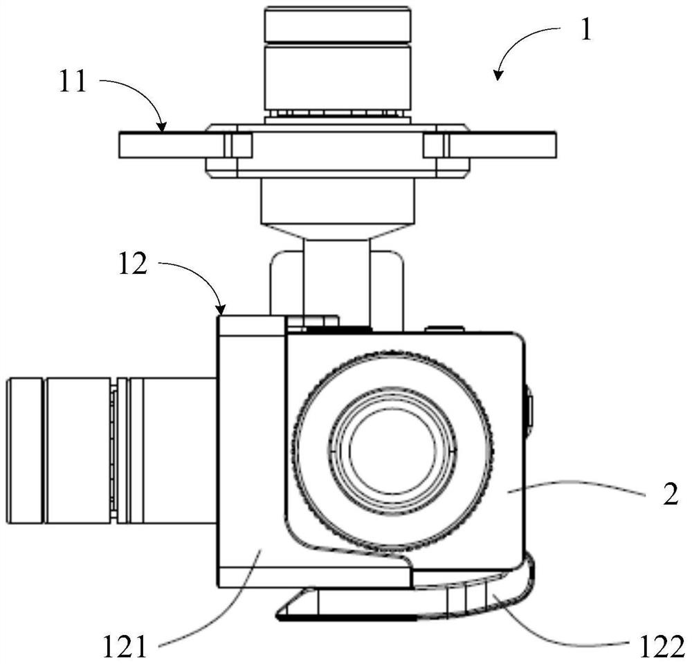
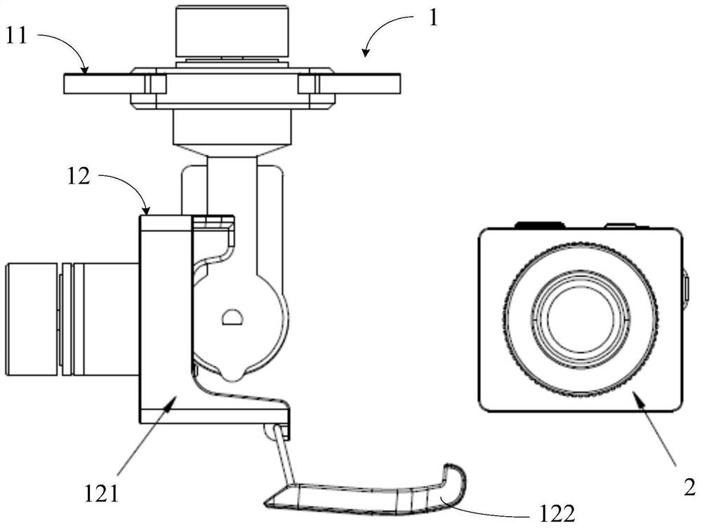
[0034] figure 1 It is a schematic diagram of a pan-tilt structure and a camera module in an assembled state shown according to an exemplary embodiment; figure 2 It is a schematic diagram showing a pan-tilt structure and a camera module in a separated state according to an exemplary embodiment. Such as Figure 1-2 As shown, in the technical solution of the present disclosure, a spli...


PUM


Abstract

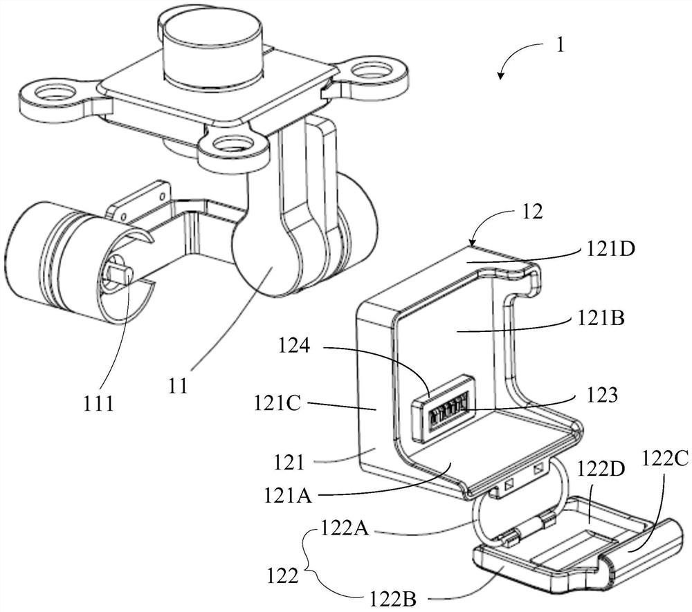
The present disclosure relates to a pan-tilt structure and a camera module. The pan-tilt structure may include: a pan-tilt body; Connected to the motor shaft of the pan-tilt body; the inner side of the fixed seat forms an accommodating space for the camera module; a limiter, the limiter can be inserted into the inner side of the fixed seat at the camera module Afterwards, the camera module is limited in the accommodation space. Through the technical solution of the present disclosure, the separate design of the pan-tilt structure and the camera module can be realized, and the stable connection and quick disassembly of the pan-tilt structure to the camera module can be ensured.

Description

technical field [0001] The present disclosure relates to the technical field of flight control, in particular to a pan-tilt structure and a camera module. Background technique [0002] Equipped with a camera module through the gimbal structure, the aircraft can be used in many fields such as aerial photography, rescue, etc., and has a very wide range of application scenarios and important functions. Of course, the camera module itself can actually be applied to general shooting scenes in daily life or work, but because the pan-tilt structure and the camera module in the related art are integrated, that is, there is no connection between the pan-tilt structure and the camera module. Separated from each other, due to the considerations of portability and use, it is often only possible to cooperate with the aircraft as a whole, resulting in a waste of resources. Contents of the invention [0003] The disclosure provides a pan-tilt structure and a camera module to solve the d...

Claims


Application Information

Patent Timeline
Patent Type & Authority Patents(China)
IPC IPC(8): H04N5/225
CPCH04N23/57
Inventor 杨容涛蔡炜叶华林
Owner BEIJING XIAOMI MOBILE SOFTWARE CO LTD
Learn More