intraosseous single tooth implant

An implant, single-tooth technology, applied in the fields of implantology, medical science, dental prosthesis, etc., can solve the problems of incomplete depth and difficulty in manufacturing.

Active Publication Date: 2020-05-15
罗格昂OMF生物活性系统有限公司
View PDF19 Cites 1 Cited by
  • Summary
  • Abstract
  • Description
  • Claims
  • Application Information

AI Technical Summary

Problems solved by technology

In terms of production, such a form-adapting element is relatively difficult to produce, wherein in some cases the complete depth without the annular seat / centering ring for centering, mounting and fixing of the spacer sleeve relative to the basic body is not particularly advantageous

Method used


Image

  • intraosseous single tooth implant
  • intraosseous single tooth implant
  • intraosseous single tooth implant

Examples


Embodiment Construction

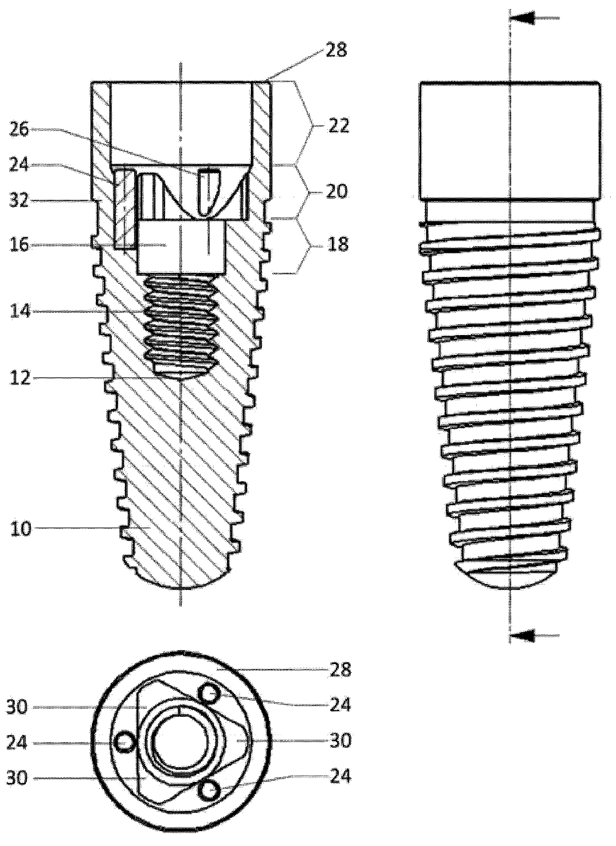
[0066]As shown in Figure 1, the single-tooth implant in the illustrated embodiment comprises a base 10 (which is closed at its top as shown in Figure 1), a bottom and a top, and has a blind hole 12 as shown in Figure 1 Open towards the coronal end as shown, the top has an internal thread 14 close to the top of the blind hole 12 . A set screw 70 (not shown in this figure) can be screwed into this internal thread. Adjacent to the internal thread 14 of the base body 10 in the coronal direction is a hollow-cylindrical annular recess 16 having a larger internal diameter than the internal thread 14 . In the form shown, the annular recess 16 has three segments (18; 20; 22).

[0067] The annular recess 16 has a guide section 18 coronally adjoining the internal thread 14 . The guide section 18 coronally adjoining the annular recess 16 is a form-adapting section 20 with a coronally increasing inner diameter relative to the guide section 18 and a conical inner wall which, in the form o...


PUM


Abstract

The invention relates to a vibration-resistant single-tooth implant for fixing a dental prosthesis, said implant comprising: a substantially cylindrical base body which can be inserted into a hole in a jawbone; an abutment which can be inserted into an annular depression of the base body and has a hole for receiving a fixing screw and a fixing head for a dental prosthesis; and a fixing screw which can be inserted into the blind hole of the base body and pass through the abutment.

Description

technical field [0001] The invention relates to an intraosseous single-tooth implant for fixing a dental prosthesis. Background technique [0002] In a single-tooth implant as known from DE 40 28 855 C2 and also the subject of DE 195 09 762.9-32, protection against rotation is provided, in which an annular recess based on the base body and a spacer sleeve form-adapting element complementary to the annular recess are provided , on the front end, a base body form-fitting element is provided for the centering ring of the spacer sleeve. In terms of production, such form-adapting elements are relatively difficult to produce, wherein in some cases the complete depth without an annular seat / centering ring for centering, mounting and fixing of the spacer sleeve relative to the base body is not particularly advantageous. [0003] A similar problem occurs with another dental implant, as proposed in DE 37 35 378, because the form-adapting elements of the base body are also at a distan...

Claims


Application Information

Patent Timeline
Patent Type & Authority Patents(China)
IPC IPC(8): A61C8/00
CPCA61C8/0054A61C8/006A61C8/0066A61C8/0068A61C8/0069A61C8/0089
Inventor W·杜尔
Owner 罗格昂OMF生物活性系统有限公司
Why Eureka
Try Eureka