Method for heating metal material in additive manufacturing
A metal material and additive manufacturing technology, applied in the field of additive manufacturing, can solve problems such as the inability to flexibly change the temperature curve of metal materials, and achieve the effect of improving the structure and mechanical properties of materials
- Summary
- Abstract
- Description
- Claims
- Application Information
AI Technical Summary
Problems solved by technology
Method used
Image

Examples
Embodiment 1
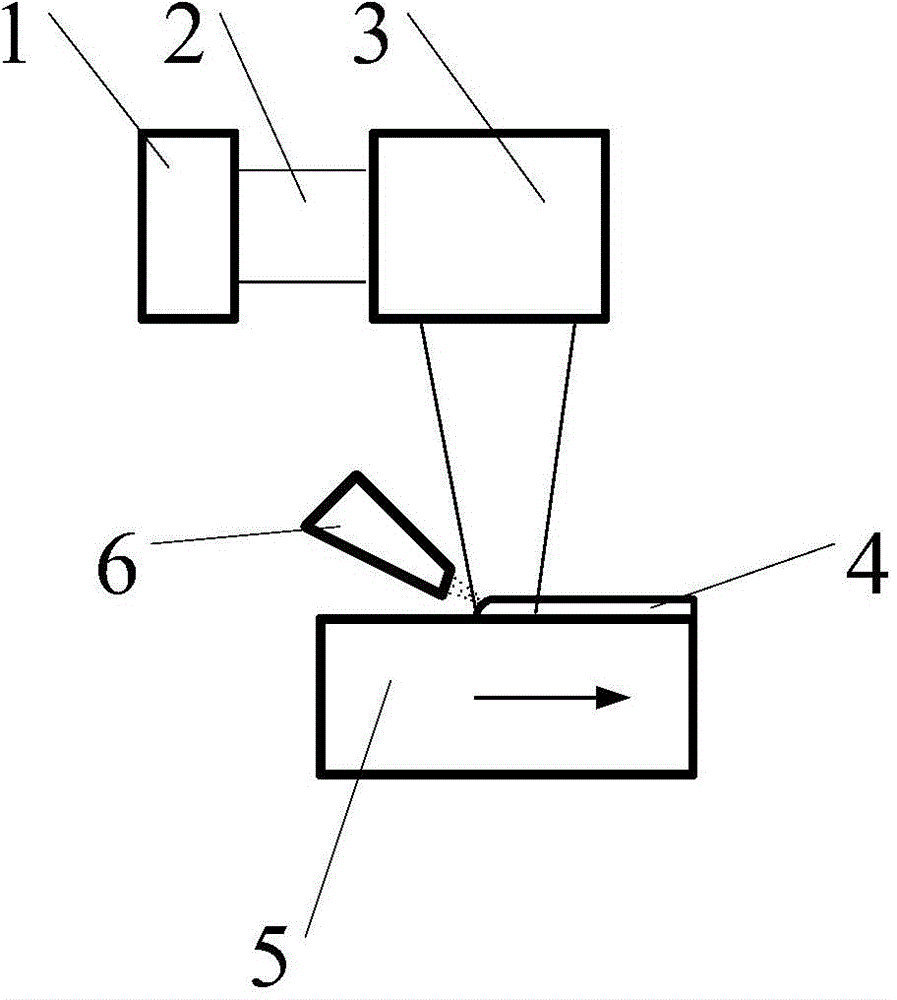
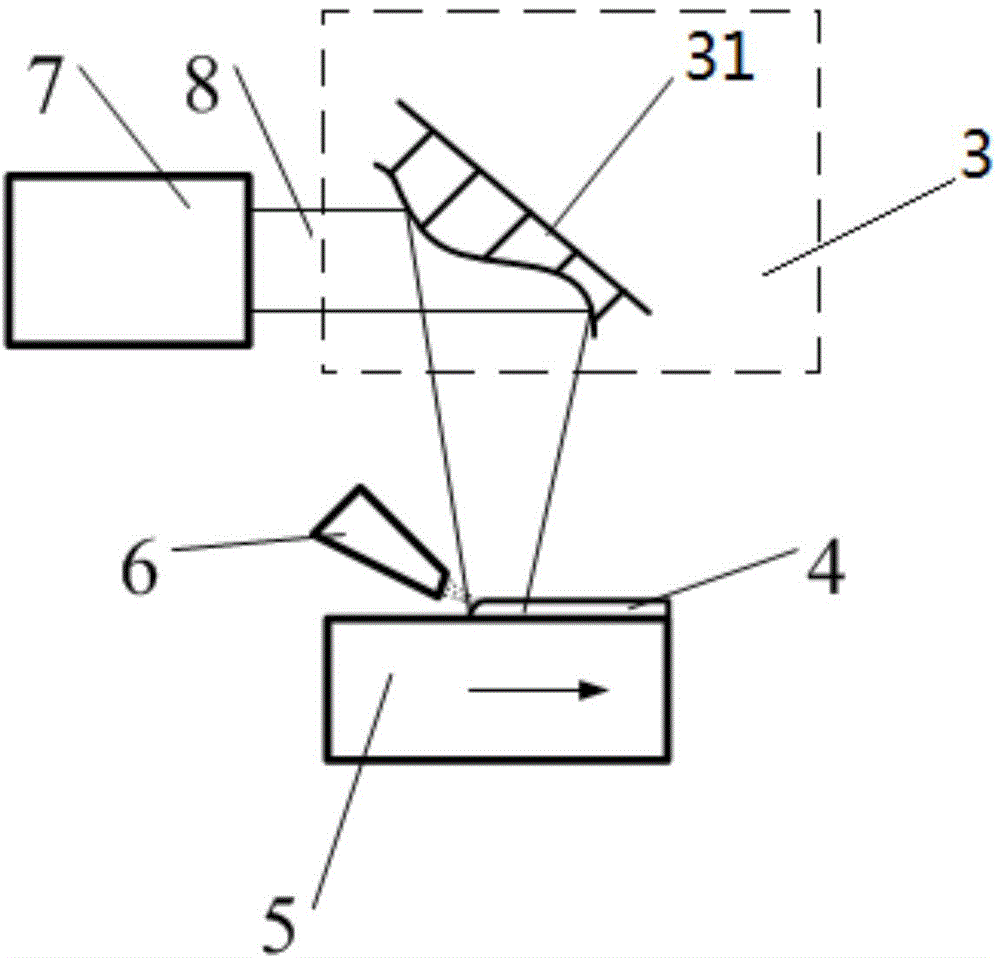
[0032] figure 2 A schematic diagram of laser additive manufacturing of metal materials is given in Embodiment 1, wherein the laser 1 is a fiber laser 7, the laser beam 2 is a single-mode laser beam 8, and the beam shaping element 3 is a deformable mirror 31. The specific steps of the metal material heating method are as follows:
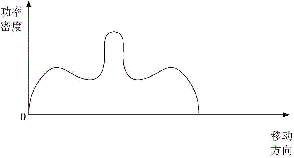
[0033] Step 1, the single-mode laser beam 8 produced by the fiber laser 7 is irradiated on the deformable mirror 31 as the beam shaping element, the phase is adjusted by the deformable mirror 31, and then reflected to the workpiece substrate 5 to form a spot; by controlling the mirror surface of the deformable mirror 31 Topography can flexibly control the power density of each spot, for example, the power density of the spot can be controlled as image 3 The distribution described in .
[0034] In step 2, the spot moves on the workpiece substrate 5 according to a preset track, and the nozzle 6 sprays the metal material to the front edge of the spot...
Embodiment 2
[0036] Figure 5 A schematic diagram of laser additive manufacturing of metal materials in Embodiment 2 is given, wherein the laser 1 selects a solid-state laser 9, the laser beam 2 adopts a multimode laser beam 10, the beam shaping element 3 includes a micromirror array 11 and a lens group 12, and the metal material heating method Specific steps are as follows:
[0037] Step 1, the multi-mode laser beam 10 generated by the solid-state laser 9 is irradiated onto the micromirror array 11, the amplitude is modulated by the micromirror array, and then focused onto the workpiece substrate 5 through the lens group 12 to form a spot. By controlling the reflection direction of each mirror surface on the micromirror array 11, light and dark changes can be flexibly produced around the spot, thereby controlling the power density of the spot, Figure 6 A spot power density distribution curve is given.
[0038] Step 2: The light spot moves on the workpiece substrate 5 according to a pre...
PUM
 Abstract
Description
Claims
Application Information
 - R&D
- Intellectual Property
- Life Sciences
- Materials
- Tech Scout
- Unparalleled Data Quality
- Higher Quality Content
- 60% Fewer Hallucinations
Browse by: Latest US Patents, China's latest patents, Technical Efficacy Thesaurus, Application Domain, Technology Topic, Popular Technical Reports.
© 2025 PatSnap. All rights reserved.Legal|Privacy policy|Modern Slavery Act Transparency Statement|Sitemap|About US| Contact US: help@patsnap.com