Supercharge Your Innovation With Domain-Expert AI Agents!

Novel mould ejection mechanism

A technology of ejection mechanism and new mold, which is applied in the field of specific parts in the mold assembly, can solve problems such as difficult to observe, mold damage, bolt loosening, etc., and achieve the effect of convenient installation and use

Inactive Publication Date: 2016-10-05
季毅
View PDF0 Cites 0 Cited by
  • Summary
  • Abstract
  • Description
  • Claims
  • Application Information

AI Technical Summary

Problems solved by technology

[0004] The general working temperature of the mold is about 170°C, and the whole mechanism is a moving part. The bolts will loosen and retreat due to temperature changes. Since the ejector mechanism is at the bottom of the mold, it is difficult to observe, and mold damage often occurs

Method used


Image

  • Novel mould ejection mechanism
  • Novel mould ejection mechanism
  • Novel mould ejection mechanism

Examples


Embodiment Construction

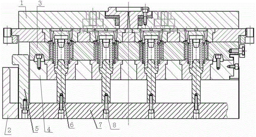
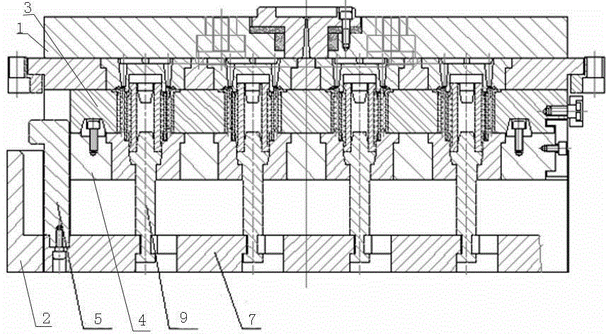
[0020] The present invention as figure 2 , 3 , 4, and 5.

[0021] A new type of mold ejection mechanism, including upper and lower bases 1, 2, upper and lower molds 3, 4 are respectively installed on the upper and lower bases 1, 2, wherein the lower mold 4 is connected with a bracket 7 through a pull rod 5, and the lower mold 4 The mold 4 is also provided with an ejector rod 9, which is characterized in that: the lower end of the ejector rod 9 is provided with a journal, and the journal is provided with a clamping groove 10, corresponding to the clamping groove 10, a clamping step 11 is provided in the bracket 7.

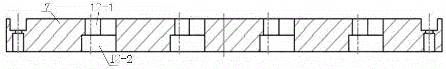
[0022] The clamping step 11 in the support bar 7 is a through step hole, wherein the step hole is an upper small hole 12-1 and a lower large hole 12-2, and the diameter of the small hole 12-1 matches the journal slot 10, and is small An opening 13 is provided on the side of the hole 12-1 transitioning toward the center.

[0023] The through step hole is a waist ...


PUM


Abstract

The invention relates to a novel mould ejection mechanism. The novel mould ejection mechanism comprises an upper base and a lower base, and an upper mould and a lower mould are mounted on the upper base and the lower base, respectively. The lower mould is connected to a supporting bar through a pull rod, ejector pins are further arranged to go through the lower mould, shaft necks are arranged at the lower ends of the ejector pins, slots are formed on the shaft necks, and clamping steps are formed in the supporting bar corresponding to the slots; the clamping steps in the supporting bar are perforative step holes, wherein the step holes comprise upper small holes and lower big holes; the diameter of the small holes is matched with the slots of the shaft necks, and openings are transitionally formed from the side edges to the centers of the small holes; the perforative step holes are waist-shaped holes. When the novel mould ejection mechanism provided by the invention is used, the clamping steps in the supporting bar clamp the slots on the shaft necks of the ejector pins, so that the ejector pins are driven to move up and down by virtue of a force of the supporting bar, and ejector pins move in the lower mould to eject a product, and therefore, a conventional bolt connecting mode is avoided, and mounting and use are facilitated.

Description

technical field [0001] The invention relates to a specific part in a mold assembly used in the production of auto parts, in particular to a novel mold ejection mechanism. Background technique [0002] In the mass production of rubber products, a special vulcanization mold is required, and the mold needs to have the characteristics of easy part forming and part ejection. [0003] Usually we install a special ejection mechanism on the lower part of the mold, but the mechanism generally adopts a threaded connection. like figure 1 As shown, upper and lower bases 1, 2 are included, and upper and lower molds 3, 4 are respectively installed on the upper and lower bases 1, 2, wherein the lower mold 3 is connected with a bracket 7 through a pull rod 5, and the lower end of the bracket 7 is passed through a bolt 8 is connected with a push rod-6, and the upper end of the push rod-6 runs through the lower mold 3 to play the role of ejecting parts. [0004] The general working tempera...

Claims


Application Information

Patent Timeline
Patent Type & Authority Applications(China)
IPC IPC(8): B29C33/44
Inventor 季毅
Owner 季毅
Features
  • R&D
  • Intellectual Property
  • Life Sciences
  • Materials
  • Tech Scout
  • Unparalleled Data Quality
  • Higher Quality Content
  • 60% Fewer Hallucinations
Learn More