
Borrow eject structure

A technology of ejecting plate and pushing plate, applied in the field of borrowed ejecting structure, can solve the problem that the convex column cannot be demolded and so on

Active Publication Date: 2018-06-19
SUZHOU MITAC PRECISION TECH
View PDF4 Cites 0 Cited by
  • Summary
  • Abstract
  • Description
  • Claims
  • Application Information

AI Technical Summary

Problems solved by technology

[0005] Therefore, the purpose of the present invention is to provide a borrowing ejection structure, which can solve the problem that the protrusion of the product interferes with the position of the KO hole on the same axis, causing the protrusion to be unable to be demolded

Method used


Image

  • Borrow eject structure
  • Borrow eject structure
  • Borrow eject structure

Examples


Embodiment Construction

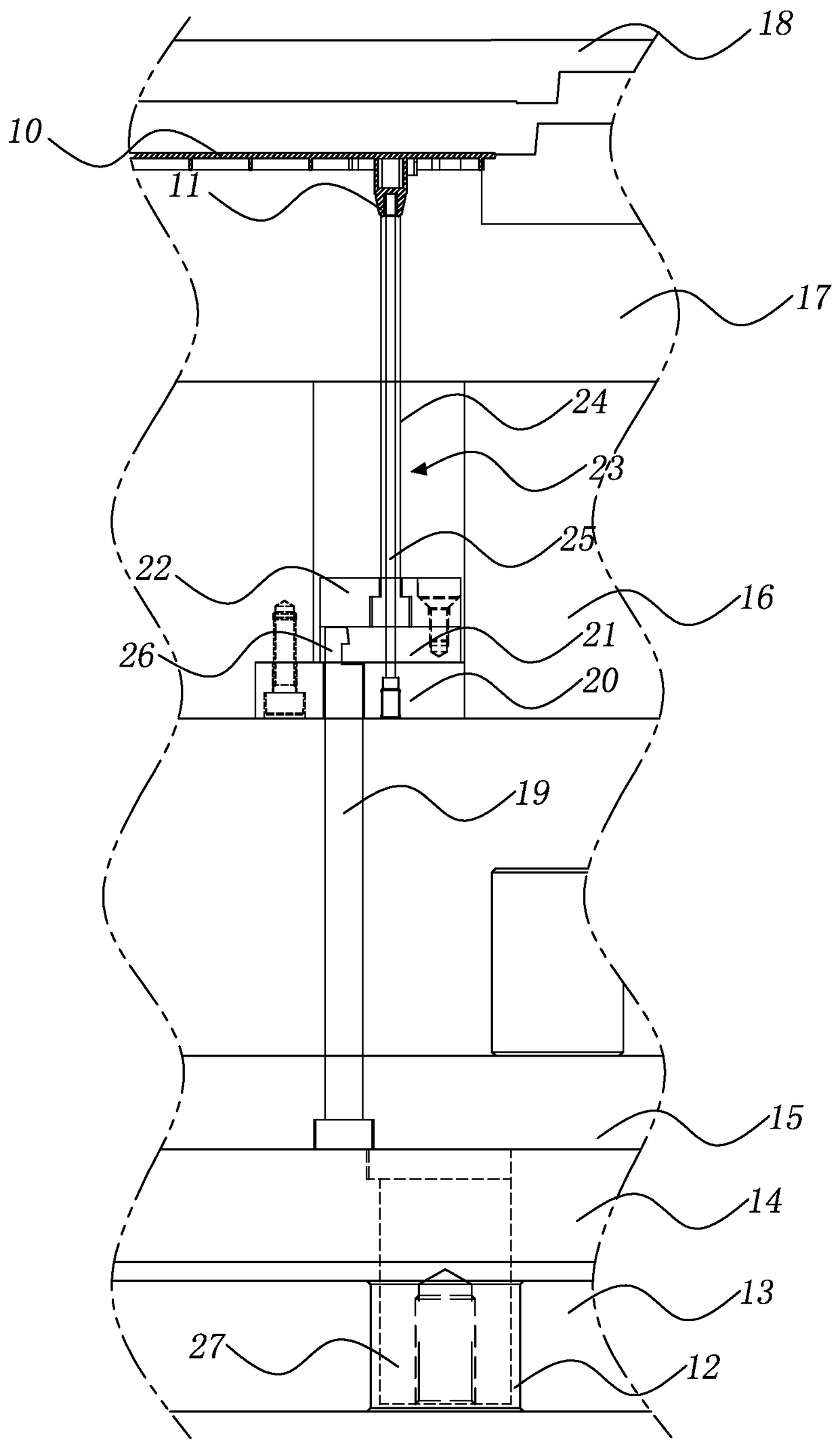
[0018] see figure 1 As shown, it depicts a schematic diagram of the borrow ejection structure of the present invention.

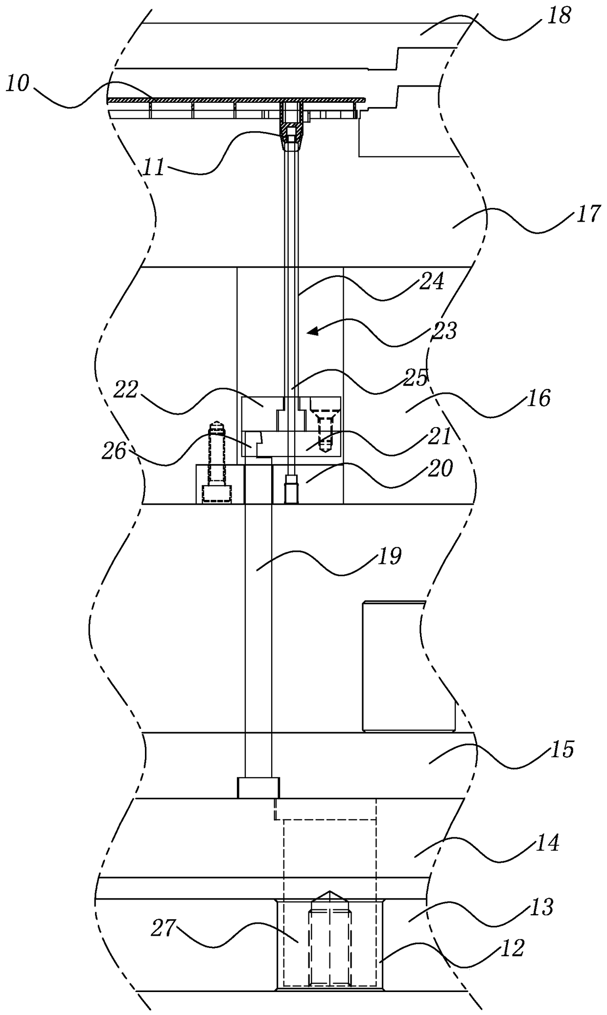
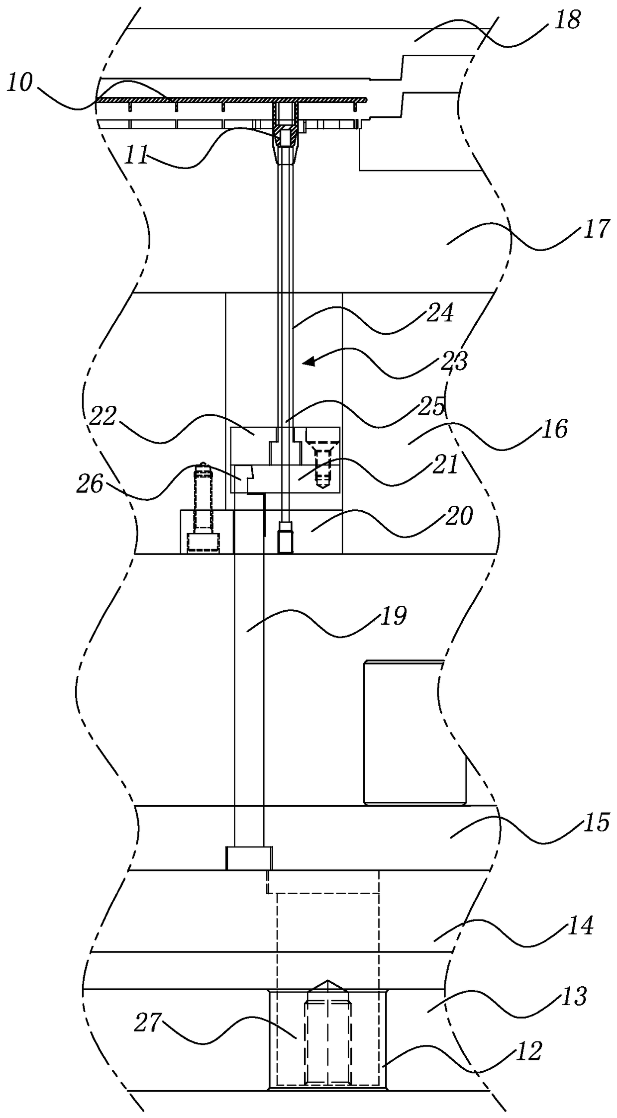
[0019] The borrowing ejection structure of the present invention is applied to molding a product 10 with a boss 11 in a mold, and the boss 11 interferes with the KO hole 12 on the same axis, and the mold includes a lower fixing plate 13, a lower top Ejection plate 14, upper ejection plate 15, male formwork 16, male mold core 17, female mold core 18 and female formwork, the borrowing ejection structure includes:

[0020] Push rod 19, one end of which is fixed in the upper ejection plate 15 by staggering the axial position of KO hole 12;

[0021] A panel 20, which is fixed in the male template 16, and the other end of the push rod 19 passes through the panel 20;

[0022] a first push plate 21, which is arranged on the panel 20, and one end of the push rod 19 abuts against the first push plate 21;

[0023] The second push plate 22 is arranged on the first p...


PUM


Abstract

A borrowing ejecting-out structure comprises a push rod, an embedding plate, a first push plate, a second push plate and an ejector sleeve. One end of the push rod is staggered from the axis position where a KO hole is formed and is fixed into an ejecting-out plate; the embedding plate is fixed into a male mold plate, and the other end of the push rod penetrates the embedding plate, the first push plate is arranged on the embedding plate, and one end of the push rod abuts against the first push plate; the second push plate is arranged on the first push plate and is connected with the first push plate; the ejector sleeve comprises a sleeve body and a core, one end of the core is fixed into the embedding plate, the outer edge of a product convex column is formed at the other end of the core, one end of the sleeve body is fixed into the second push plate, and the other end of the sleeve body stretches into the product convex column; and the borrowing ejecting-out structure can well solve the problems that the product convex column and the KO hole intervene with each other on the same axis line, and the product convex column cannot be subject to demolding.

Description

【Technical field】 [0001] The invention relates to an ejection structure of a mold, in particular to a borrowing ejection structure. 【Background technique】 [0002] When injecting products, there are often bosses (BOSS pillars) on the product. If there is interference between the center position and the KO hole position on the same axis, the ejector pin of the machine will pass through the lower fixing plate of the mold and press against the ejector plate of the mold, and the core end of the cylinder has no position to be fixed on the mold. In the lower fixed plate, it is impossible to use the cylinder to release the mold. [0003] If inserting pins are used instead of cylinders, the product cannot be demoulded during mold testing; if cylinders are used for demoulding, the ejector pin is not ejected at the KO hole, which will cause unbalanced ejection and cause the oblique pin of the mold to be easily stuck die. [0004] In view of this, it is necessary to develop a borrow...

Claims


Application Information

Patent Timeline
Patent Type & Authority Patents(China)
IPC IPC(8): B29C45/40
Inventor 孟强
Owner SUZHOU MITAC PRECISION TECH
Learn More