Method for controlling electronic lock, electronic lock, key terminal and lock cylinder terminal

A technology for controlling electronics and the main control terminal, applied in the field of smart locks, can solve problems such as large quantities, failure to open the cabinet normally, and failure of active electronic locks to work, so as to achieve the effect of reducing operation and maintenance costs and complexity

Inactive Publication Date: 2016-10-05
ZTE CORP +1
View PDF7 Cites 3 Cited by
  • Summary
  • Abstract
  • Description
  • Claims
  • Application Information

AI Technical Summary

Problems solved by technology

[0007] The active electronic lock requires a power supply inside the box. Once the box is locked and the power supply inside the box is exhausted, the active electronic lock will not work, resulting in the box being locked and unable to open normally.
In order to prevent the box from being unable to open normally due to the exhaustion of the internal power supply of the box, it is necessary to regularly maintain the internal power supply of the box in a large number of boxes, such as regularly charging a large number of internal power supplies of the box, usually the number of internal power supplies of the box that needs to be maintained is very large , which makes the maintenance of the internal power supply of the box very complicated, which obviously increases the operation and maintenance complexity of the lock management system, thereby increasing the operation and maintenance cost of the communication network

Method used


Image

  • Method for controlling electronic lock, electronic lock, key terminal and lock cylinder terminal
  • Method for controlling electronic lock, electronic lock, key terminal and lock cylinder terminal

Examples


Embodiment Construction

[0051] In order to make the purpose, technical solution and advantages of the present invention more clear, the embodiments of the present invention will be described in detail below in conjunction with the accompanying drawings. It should be noted that, in the case of no conflict, the embodiments in the present application and the features in the embodiments can be combined arbitrarily with each other.

[0052] The steps shown in the flowcharts of the figures may be performed in a computer system, such as a set of computer-executable instructions. Also, although a logical order is shown in the flowcharts, in some cases the steps shown or described may be performed in an order different from that shown or described herein.

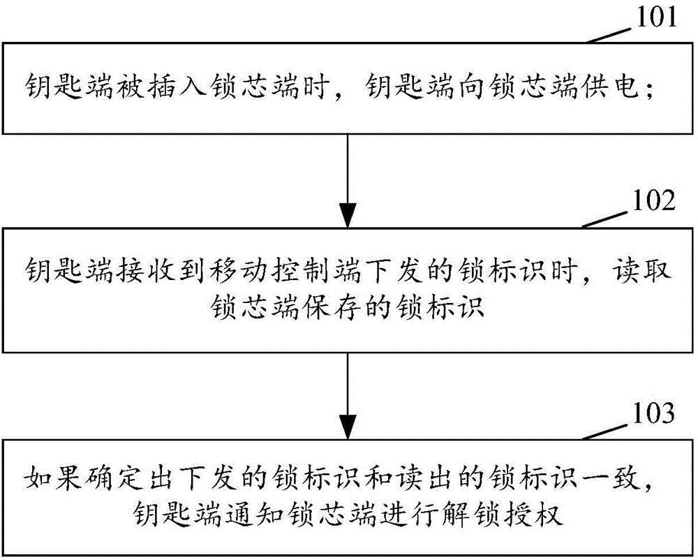
[0053] figure 1 It is the flow chart of the method for controlling electronic lock of the present invention, as figure 1 shown, including:

[0054] Step 101: When the key end is inserted into the lock cylinder end, the key end supplies power to the lock...


PUM


Abstract

The invention discloses a method for controlling an electronic lock, the electronic lock, a key terminal and a lock cylinder terminal. The method comprises the following steps that when the key terminal is inserted into the lock cylinder terminal, the key terminal supplies power to the lock cylinder terminal; when the key terminal receives a lock mark transmitted by a mobile control terminal, the key terminal reads a lock mark stored by the lock cylinder terminal; and if it is determined that the transmitted lock mark is identical to the read lock mark, the key terminal informs the lock cylinder terminal of unlocking and authorization. According to the invention, an internal power supply in a case is prevented from supplying power to the electronic lock, so considerable regular maintenance of the internal power supply in the case is avoided, and complexity in operation and maintenance of a lock management system is reduced; and thus, operation and maintenance cost for a communication network is decreased.

Description

technical field [0001] The invention relates to intelligent lock technology, in particular to a method for controlling an electronic lock, an electronic lock, a key end and a lock cylinder end. Background technique [0002] In order to effectively manage the extremely large number of various boxes in the communication network operated and maintained by the operator, such as the keys of the racks used to place communication equipment, to reduce the maintenance complexity of a large number of keys and improve the security of a large number of boxes, the operation Lock management systems are widely adopted by vendors. The lock management system realizes the comprehensive management of a large number of cabinets, including authorizing functions such as unlocking and locking specific cabinets according to work requirements. [0003] In order to improve manageability, lock management systems usually use active electronic locks as unlocking components for a large number of cabinet...

Claims


Application Information

Patent Timeline
IPC IPC(8): G07C9/00E05B47/00
CPCE05B47/00E05B49/00
Inventor 郝祥勇马爱萍龚裕姚春良丁汉平
Owner ZTE CORP
Why Eureka
Try Eureka