Cooling wet-desulphurization smoke demisting device
A technology of wet desulfurization and demisting device, which is applied in the direction of combination device, separation method, steam condensation, etc. It can solve the problems that the wet desulfurization flue gas demisting cannot be completely completed, and the blockage of the demister can not be solved, so as to avoid blockage , Strengthen the effect of capture
- Summary
- Abstract
- Description
- Claims
- Application Information
AI Technical Summary
Problems solved by technology
Method used
Image

Examples
Embodiment 1
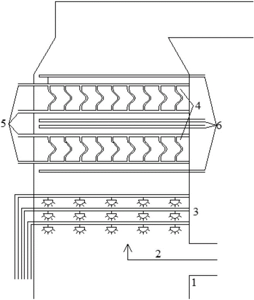
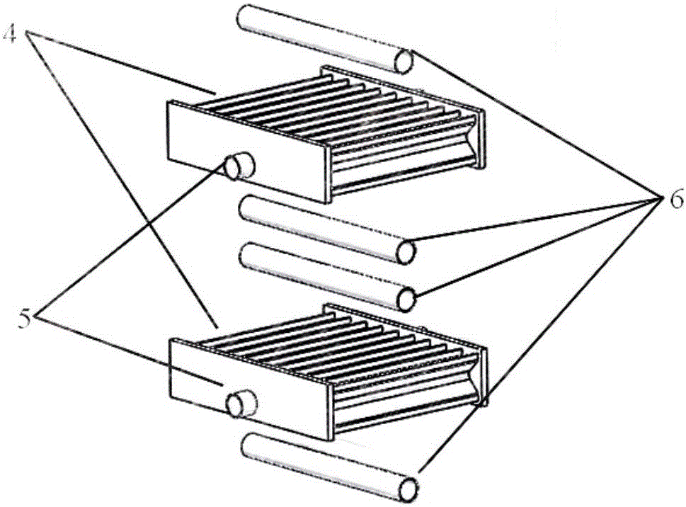
[0023] refer to figure 2 , the cooling demister 4 is a cooling flat plate demister, and the number of flushing devices 6 arranged above and below the cooling demister 4 on each layer is one; the flue gas passes through the flue gas inlet 2 of the wet desulfurization tower 1 After entering the wet desulfurization tower 1 and passing through the spray layer 3, small droplets of desulfurization slurry will be entrained in the flue gas, and then the flue gas passes through two layers of cooling flat plate demisters, cooling flat plate demisters and cooling water pipes The road 5 is connected, the cooling water pipe 5 is passed into the cooling water, and the cooling water enters the blades of the cooling flat plate demister, the temperature of the cooling water is lower than the temperature of the flue gas, and the cooling flat plate demister plays a cooling role , so that the temperature of the cooling flat plate demister is lower than the temperature of the flue gas. When the f...
Embodiment 2
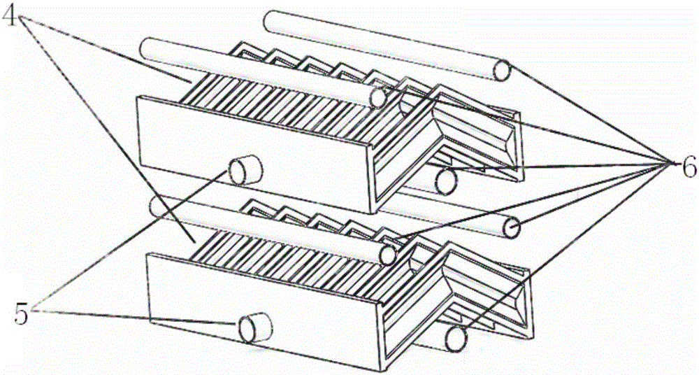
[0025] Such as image 3 As shown, the cooling type demister 4 is a roof type demister, wherein the number of flushing devices 6 arranged above and below each layer of the cooling type demister 4 is two, and the roof type demister and the cooling water pipeline 5-phase connection, the cooling water pipeline 5 is fed with cooling water, and the cooling water enters the blades of the roof-type mist eliminator. The temperature of the roof-type demister is lower than the temperature of the flue gas. When the flue gas passes through the roof-type demister, the temperature drops, and part of the water vapor condenses on the small droplets, which makes the small droplets absorb moisture and grow up. Under the action, it hits the roof-type mist eliminator, and at the same time, the small droplets are also affected by the thermophoretic force of the low-temperature object on the higher-temperature droplets, and are more likely to be captured by the roof-type mist eliminator. The flushi...
Embodiment 3
[0027] Such as Figure 4 As shown, the cooling type demister 4 includes a roof type demister and some column pipes 7, and each column tube 7 is positioned under the cooling type roof type demister, and the cooling water pipeline 5 is connected with the cooling type roof type demister and each The column pipes 7 are connected, wherein, the number of flushing devices 6 arranged above and below the cooling type demister 4 of each layer is 2, the roof type demister and the column pipe 7 are connected with the cooling water pipeline 5, and the cooling water pipe The cooling water is passed into the road 5, and the cooling water enters the roof type demister and the column tube 7, the temperature of the cooling water is lower than the temperature of the flue gas, and the cooling water plays a cooling role on the roof type demister and the column tube 7, The temperature of the ridge type demister and the column tube 7 is lower than the temperature of the flue gas. When the flue gas p...
PUM
 Abstract
Description
Claims
Application Information
 - R&D
- Intellectual Property
- Life Sciences
- Materials
- Tech Scout
- Unparalleled Data Quality
- Higher Quality Content
- 60% Fewer Hallucinations
Browse by: Latest US Patents, China's latest patents, Technical Efficacy Thesaurus, Application Domain, Technology Topic, Popular Technical Reports.
© 2025 PatSnap. All rights reserved.Legal|Privacy policy|Modern Slavery Act Transparency Statement|Sitemap|About US| Contact US: help@patsnap.com