Novel strength controllable pressure roller device
A pressure roller device and a new type of technology are applied in the components of the pumping device for elastic fluids, the liquid variable volume machinery, the variable volume pump components, etc., which can solve the problems affecting the processing effect of materials, etc. Quantization, simple structure and low weight, the effect of reducing weight
- Summary
- Abstract
- Description
- Claims
- Application Information
AI Technical Summary
Problems solved by technology
Method used
Image

Examples
Embodiment 1
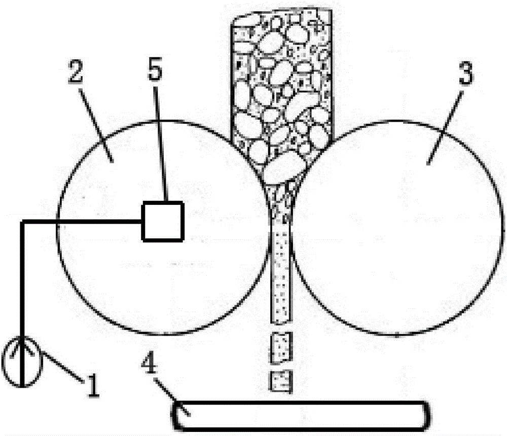
[0032] Such as figure 1 A new type of highly controllable pressure roller device shown includes a driving pressure roller 2, a driven pressure roller 3 and a conveying belt 4, and the material falls from above the gap between the driving pressure roller 2 and the driven pressure roller 3, After being rolled, it falls into the conveying belt 4; the active pressure roller 2 is driven to rotate by a hydraulic motor 5, and the hydraulic motor 5 is supplied with oil by an oil supply pump; the oil supply pump is a giant magnetostrictive pump 1. The circumferential surfaces of the active pressing roller 2 and the driven pressing roller 3 are provided with a plurality of tooth grooves for convenient rolling. The hydraulic motor 5 is arranged at the end of the rotating shaft of the active pressure roller 2 . The conveying belt 4 is provided with a weight sensor for sensing the weight of the material on the conveying belt 4. The speed control of the conveying belt 4 is based on the mat...
Embodiment 2
[0043] Such as figure 1 A new type of highly controllable pressure roller device shown includes a driving pressure roller 2, a driven pressure roller 3 and a conveying belt 4, and the material falls from above the gap between the driving pressure roller 2 and the driven pressure roller 3, After being rolled, it falls into the conveying belt 4; the active pressure roller 2 is driven to rotate by a hydraulic motor 5, and the hydraulic motor 5 is supplied with oil by an oil supply pump; the oil supply pump is a giant magnetostrictive pump 1. The circumferential surfaces of the active pressing roller 2 and the driven pressing roller 3 are provided with a plurality of tooth grooves for convenient rolling. The hydraulic motor 5 is arranged at the end of the rotating shaft of the active pressure roller 2 . The conveying belt 4 is provided with a weight sensor for sensing the weight of the material on the conveying belt 4. The speed control of the conveying belt 4 is based on the mat...
Embodiment 3
[0054] Such as figure 1 A new type of highly controllable pressure roller device shown includes a driving pressure roller 2, a driven pressure roller 3 and a conveying belt 4, and the material falls from above the gap between the driving pressure roller 2 and the driven pressure roller 3, After being rolled, it falls into the conveying belt 4; the active pressure roller 2 is driven to rotate by a hydraulic motor 5, and the hydraulic motor 5 is supplied with oil by an oil supply pump; the oil supply pump is a giant magnetostrictive pump 1. The circumferential surfaces of the active pressing roller 2 and the driven pressing roller 3 are provided with a plurality of tooth grooves for convenient rolling. The hydraulic motor 5 is arranged at the end of the rotating shaft of the active pressure roller 2 . The conveying belt 4 is provided with a weight sensor for sensing the weight of the material on the conveying belt 4. The speed control of the conveying belt 4 is based on the mat...
PUM
 Abstract
Description
Claims
Application Information