Reciprocating pump

A technology of reciprocating pump and reciprocating mechanism, applied in the field of reciprocating pump, can solve the problems of large occupied space, large impact pulsation, complex structure, etc., and achieve the effect of less device parts, small impact pulsation, stable and reliable movement

Active Publication Date: 2010-08-04
ZHEJIANG UNIV OF TECH
View PDF0 Cites 0 Cited by
  • Summary
  • Abstract
  • Description
  • Claims
  • Application Information

AI Technical Summary

Problems solved by technology

[0003] The invention aims to solve the problems of complex structure, large space occupation, large impact pulsation, high noise and short life of the traditional reciprocating pump, and provides a compact structure, small occupation space, small impact pulsation, low noise, Long life reciprocating pump

Method used


Image

  • Reciprocating pump
  • Reciprocating pump
  • Reciprocating pump

Examples


Embodiment Construction

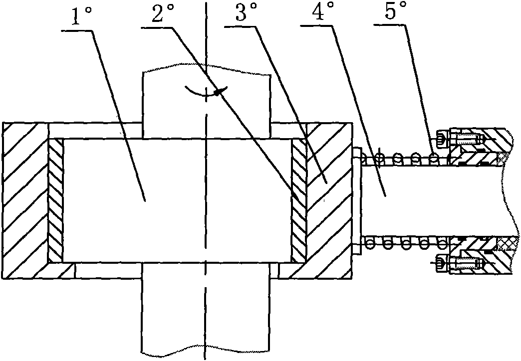
[0015] refer to Figure 4-6 , a reciprocating pump, composed of a transmission end structure and a hydraulic end structure, the transmission end structure includes a fuselage 8, a reciprocating mechanism, the reciprocating mechanism includes a connecting rod 1, a plunger 4, and a crankshaft 2, and the crankshaft 2 is provided with There is a supporting bearing 5, and a connecting rod bearing 3 is installed between the connecting rod 1 and the crank throw 6 of the crankshaft 2, and the connecting rod bearing 3 is eccentric relative to the supporting bearing 5, and the inner hole of the connecting rod 1 is formed from the upper and lower Two semicircular arcs 11 are connected with the middle straight section 12, the connecting rod bearing 3 is in contact with the straight section 12 of the inner hole of the connecting rod 1, and the connecting rod head 13 of the connecting rod 1 is connected with the plunger 4 .

[0016] A retaining ring 7 is arranged below the connecting rod b...


PUM


Abstract

The invention discloses a reciprocating pump, which consists of a driving end structure and a hydraulic end structure, wherein the driving end structure comprises a machine body and a reciprocating mechanism; the reciprocating mechanism comprises a connecting rod, a plunger piston and a crankshaft; the crankshaft is provided with a supporting bearing; a connecting rod bearing is arranged between the connecting rod and a crank of the crankshaft and is eccentric relative to the supporting bearing; an inner hole of the connecting rod is formed by connecting upper and lower semicircles and a middle straight-line segment; the connecting rod bearing is in contact connection with the straight-line segment of the inner hole of the connecting rod; and a connecting rod head of the connecting rod is connected with the plunger piston. The reciprocating pump has the advantages that: on the whole, the reciprocating pump has few parts, a compact structure and a small occupied space and saves materials; in addition, as the connecting rod only produces transitional motions and does not rotate and swing, impact pulse is decreased, noise is reduced and the motions are more stable and reliable.

Description

technical field [0001] The invention relates to a reciprocating pump. Background technique [0002] The reciprocating mechanism is the main part of the reciprocating pump, which can convert the rotary motion of the crankshaft into the reciprocating linear motion of the piston (plunger), and then periodically change the volume to achieve the function of conveying the medium. There are three main types of reciprocating structures in traditional reciprocating pumps, such as: figure 1 , figure 2 , image 3 shown, where figure 1 The reciprocating mechanism includes crankshaft 1', connecting rod 3', crosshead 6', crosshead pin 5', bearing bush 2', bearing 4', and connecting rod 3' realizes the rotation of crankshaft 1' to the reciprocation of crosshead 6' For the conversion of motion, the crankshaft 1' drives most of the mass of the connecting rod 3' to perform a rotary motion together, thereby realizing the linear reciprocating motion of a small part of the mass of the conne...

Claims


Application Information

Patent Timeline
Patent Type & Authority Applications(China)
IPC IPC(8): F04B9/02
Inventor 张生昌徐垚英邓鸿英张鹤周深彪任洪勇
Owner ZHEJIANG UNIV OF TECH
Why Eureka
Try Eureka