
Energy-absorbing box punching mold

An energy-absorbing box and punching technology, which is applied in the field of auto parts manufacturing, can solve problems such as lack of dimensional accuracy, insufficient stability of parts processing, and consumption of equipment capacity, so as to achieve production efficiency and equipment capacity improvement, and save manpower and equipment Cost, punching positioning simple effect

Active Publication Date: 2018-01-12
辉泰(太仓)汽配有限公司
View PDF8 Cites 0 Cited by
  • Summary
  • Abstract
  • Description
  • Claims
  • Application Information

AI Technical Summary

Problems solved by technology

[0003] Generally, the method of machining holes is used to directly process the energy-absorbing box, which saves the cost of the mold, but from the perspective of parts: ① parts need to be processed on multiple sides, repeated picking and placing will cause multiple positioning, and the processing of parts The stability is not good enough; ②Dimensional accuracy will be lacking; ③The processing time is long, which consumes the capacity of the equipment
From the operator's point of view: ①The operation needs to be more precise and complete, and there will be certain safety hazards when tired; ②Once the operation is not placed in a fixed positioning position carelessly, the second is that the parts cannot meet the requirements, and there may be two Secondary processing will scrap more products, resulting in greater property losses

Method used


Image

  • Energy-absorbing box punching mold
  • Energy-absorbing box punching mold
  • Energy-absorbing box punching mold

Examples


Embodiment Construction

[0018] The following will clearly and completely describe the technical solutions in the embodiments of the present invention. Obviously, the described embodiments are only some of the embodiments of the present invention, rather than all the embodiments. Based on the embodiments of the present invention, all other embodiments obtained by persons of ordinary skill in the art without making creative efforts belong to the protection scope of the present invention.

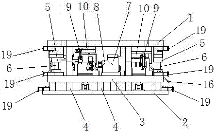
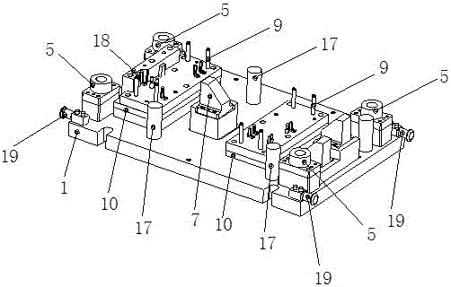
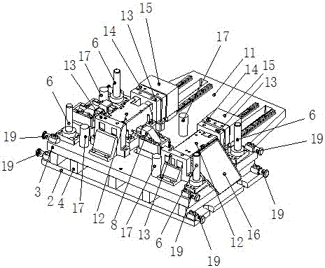
[0019] like Figure 1 to Figure 3 As shown, embodiments of the present invention include:

[0020] A punching mold for an energy-absorbing box, comprising an upper template 1, a lower template 2, a press plate 3, a die foot 4, a guide sleeve 5, an inner guide post 6, an upper mold wedge 7, a lower mold wedge 8, and guide rails Mechanism, the upper template 1, the lower template 2 and the press plate 3 are all rectangular structures of equal size, the described press plate 3 is arranged on the upper part of the lower...


PUM


Abstract

The invention discloses an energy sucking box punching mold. The energy sucking box punching mold comprises an upper template, a lower template, a press plate, a mold leg, a guide sleeve, an inner guide column, an upper mold wedge, a lower mold wedge and guide rail mechanisms; the upper template and the press plate are fixedly connected through the guide sleeve and the inner guide column matched with each other; the upper mold wedge is arranged in the middle position of the upper template; the lower mold wedge is arranged in the middle position of the press plate, and is corresponding to the upper mold wedge; the guide rail mechanisms are respectively arranged on two sides of the lower mold wedge; and the upper template is connected with the guide rail mechanisms through multiple punches. Through the mode, the energy sucking box punching mold, provided by the invention, is compact in structure, high in efficiency and excellent in size precision and stability of produced parts, adopts a punching mold procedure to finish, is simple in punching positioning, excellent in positioning and simple in operation of operators, relatively improves the safety, greatly improves the production efficiency and the equipment yield, and saves a lot of labors and equipment costs.

Description

technical field [0001] The invention relates to the manufacturing field of automobile parts; in particular, it relates to some automobile bumper energy-absorbing box parts, in particular to a punching mold for the energy-absorbing box. Background technique [0002] The energy-absorbing box is an important energy-absorbing and shock-absorbing part of the car bumper. The size of the part, the integrity and precision of the parts directly affect the fit and installation between the car bumper and the energy-absorbing box. safety. [0003] Generally, the method of machining holes is used to directly process the energy-absorbing box, which saves the cost of the mold, but from the perspective of parts: ① parts need to be processed on multiple sides, repeated picking and placing will cause multiple positioning, and the processing of parts The stability is not good enough; ②Dimensional accuracy will be lacking; ③The processing time is long, which consumes the capacity of the equipm...

Claims


Application Information

Patent Timeline
Patent Type & Authority Patents(China)
IPC IPC(8): B21D28/34B21D43/00
CPCB21D28/34B21D43/003
Inventor 余良娟
Owner 辉泰(太仓)汽配有限公司
Learn More