
Tail frame forming mold

A technology for molding molds and molds, which is applied to casting molding equipment, casting molds, cores, etc., can solve the problems of shortening the service life of molds, long prying time, and high scrap rate, so as to ensure molding quality, improve demoulding efficiency, The effect of increasing production profit

Inactive Publication Date: 2016-10-12
南京力源轨道交通装备有限公司
View PDF0 Cites 0 Cited by
  • Summary
  • Abstract
  • Description
  • Claims
  • Application Information

AI Technical Summary

Problems solved by technology

[0002] The existing tail frame forming mold uses the upper mold and the lower mold to fasten each other to form the tail frame process cavity, and then injects the slurry to form it. After the tail frame is formed, it needs to be demoulded. The existing demoulding method mainly uses manual Prying one or both ends of the mold is not only time-consuming and labor-intensive, but also takes a long time, and the tail frame stays in the mold for a long time, which will cause deformation of the mold surface and shorten the service life of the mold. The pried part is very easy to be damaged, resulting in a very high scrap rate

Method used


Image

  • Tail frame forming mold

Examples


Embodiment Construction

[0010] Below in conjunction with accompanying drawing and specific embodiment, further illustrate the present invention, should be understood that these embodiments are only for illustrating the present invention and are not intended to limit the scope of the present invention, after having read the present invention, those skilled in the art will understand various aspects of the present invention Modifications in equivalent forms all fall within the scope defined by the appended claims of this application.

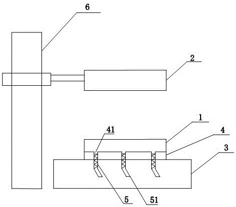
[0011] Such as figure 1 As shown, the present invention provides a tail frame molding die, comprising a lower die 1 positioned on a bracket 3 and an upper die 2 positioned directly above the lower die 1 and connected to a hydraulic lifting pump 6, between the lower die 1 and the bracket 3 A fixed frame 4 is also provided, and the fixed frame 4 is provided with three threaded through holes 41 connecting the lower mold 1 and the support 3, and the three threaded through ho...


PUM


Abstract

The invention discloses a mold for forming a tail frame, which comprises a lower mold on a bracket and an upper mold directly above the lower mold and connected to a hydraulic lifting pump, a fixing frame is also arranged between the lower mold and the bracket, and the fixing The frame is provided with at least three threaded through holes connecting the lower mold and the bracket, and the threaded through holes are evenly arranged on the fixed frame horizontally, and the threaded through holes are provided with threaded rods that match the threaded through holes. The top surface of the threaded rod coincides completely with the opening surface of the threaded through hole. The invention has its own demoulding device, which avoids the problems of time-consuming and laborious demoulding, high strength, and easy damage to the mold and molding tail frame caused by manual prying. It not only greatly improves the demoulding efficiency, Moreover, the molding quality of the tail frame after demoulding is guaranteed, the scrap rate is greatly reduced, and the production profit is improved.

Description

technical field [0001] The invention specifically relates to a mold for forming a tail frame. Background technique [0002] The existing tail frame forming mold uses the upper mold and the lower mold to fasten each other to form the tail frame process cavity, and then injects the slurry to form it. After the tail frame is formed, it needs to be demoulded. The existing demoulding method mainly uses manual Prying one or both ends of the mold is not only time-consuming and labor-intensive, but also takes a long time, and the tail frame stays in the mold for a long time, which will cause deformation of the mold surface and shorten the service life of the mold. The pried part is very prone to damage, resulting in a very high scrap rate. Contents of the invention [0003] Purpose of the invention: In order to overcome the deficiencies in the prior art, provide a tail frame forming mold that is simple, fast and effective to remove from the mold and can avoid damage to the tail f...

Claims


Application Information

Patent Timeline
Patent Type & Authority Applications(China)
IPC IPC(8): B22C9/22B22D29/04
CPCB22C9/22B22D29/04
Inventor 扶香荣姬传堂韦高春汤世海
Owner 南京力源轨道交通装备有限公司
Learn More