Repair tooling and repair method for the through shaft hole of the through bridge
A through-shaft and repairing technology, which is applied in the direction of manufacturing tools, metal processing equipment, milling machine equipment details, etc., can solve the problems of heavy repairing workload and high repairing cost, and achieve the effect of small repairing workload, low repairing cost and convenient portability
- Summary
- Abstract
- Description
- Claims
- Application Information
AI Technical Summary
Problems solved by technology
Method used
Image
Examples
Embodiment 1
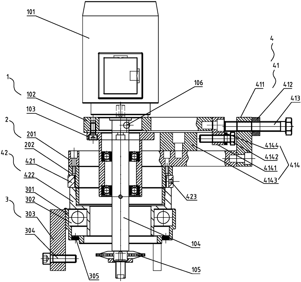
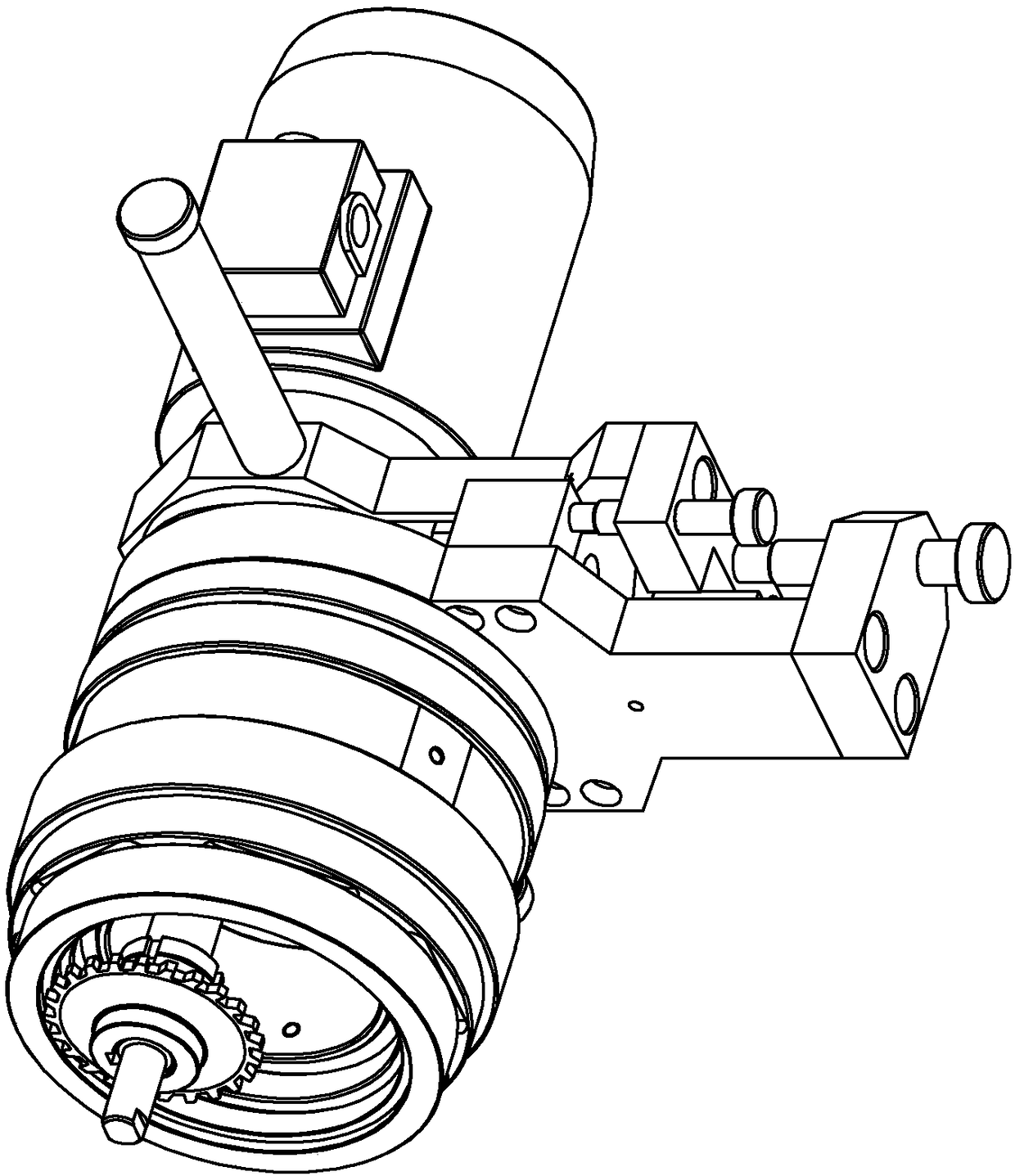
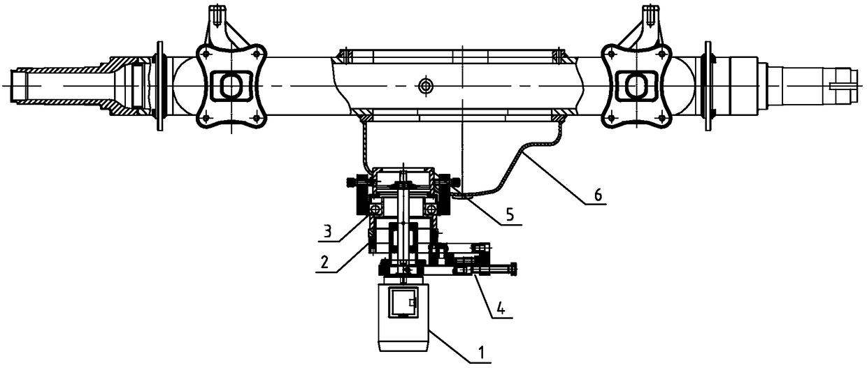
[0061] A through-bridge through-axis hole rework tooling, including a tool part 1, a rotary part 2, a positioning part 3, and an adjustment part 4. The tool part 1 includes a rotary power mechanism 101, an upper connecting plate 102, a tool holder 103, and a tool bar 104. Milling cutter 105, the rotary power mechanism 101 is installed above the upper connecting plate 102, the output shaft of the rotary power mechanism 101 is connected with one end of the cutter bar 104, and the other end of the cutter bar 104 is connected with the milling cutter 105, and the cutter The rod 104 is covered with the knife sleeve 103, and the upper connecting plate 102 is also equipped with a handle 106; And the milling cutter 105 passes through the middle hole of the upper connecting plate 102, the rotating part 2 and the positioning part 3 in turn and stretches out of the positioning part 3.
[0062] The rotating part 2 includes a lower connecting plate 201 and a supporting sleeve 202, the lower...
Embodiment 2
[0069] A method for repairing a through shaft hole of a through bridge, the method comprising the following steps:
[0070] A. Tool change:
[0071] A1. Loosen the nut on the milling cutter, and take out the nut, cutter shim and milling cutter in sequence;
[0072] A2. Take a new milling cutter, and reinstall it according to the milling cutter, cutter shim and nut in turn;
[0073] A3. Clean up the residual iron filings on the positioning sleeve 301, and insert the tool setting block to make it fit the positioning sleeve 301;
[0074] A4. Loosen the locking nut 412 and the adjusting bolt 413 of the lateral adjustment part 41, so that the cutter part 1 and the rotary part 2 can slide relatively laterally;
[0075] A5. Loosen the fastening screw I423 of the longitudinal adjustment part 42, and rotate the position of the adjustment nut 421, so that the rotary part and the positioning part can slide longitudinally relative to each other, so that the cutter surface of the milling...
PUM
 Abstract
Description
Claims
Application Information
 - R&D
- Intellectual Property
- Life Sciences
- Materials
- Tech Scout
- Unparalleled Data Quality
- Higher Quality Content
- 60% Fewer Hallucinations
Browse by: Latest US Patents, China's latest patents, Technical Efficacy Thesaurus, Application Domain, Technology Topic, Popular Technical Reports.
© 2025 PatSnap. All rights reserved.Legal|Privacy policy|Modern Slavery Act Transparency Statement|Sitemap|About US| Contact US: help@patsnap.com


