Simple floating type workbench mechanism

A workbench, floating technology, applied in the direction of metal processing machinery parts, manufacturing tools, metal processing equipment, etc., can solve the problems of increasing the overall weight of the workbench, affecting the transmission and adjustment accuracy, and difficult to form position adjustment, so as to improve the overall The effect of motion adjustment accuracy, reliable device structure and convenient use

Inactive Publication Date: 2016-10-12
王启先
View PDF6 Cites 0 Cited by
  • Summary
  • Abstract
  • Description
  • Claims
  • Application Information

AI Technical Summary

Problems solved by technology

This type of adjustment tends to increase the overall weight of the table because the overall weight of the slave drive exists as a load on the master drive
However, it is difficult to form precise position adjustment by using equal adjustment methods.
And it is easy to form a gap at the transmission part, thus affecting the transmission and adjustment accuracy

Method used


Image

  • Simple floating type workbench mechanism
  • Simple floating type workbench mechanism
  • Simple floating type workbench mechanism

Examples


Embodiment Construction

[0014] Combine below Figure 1-4 The present invention will be described in detail.

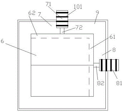
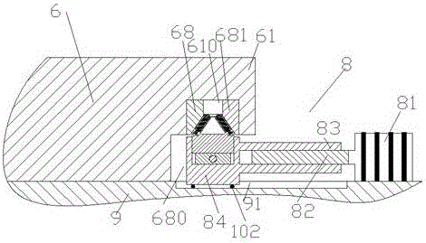
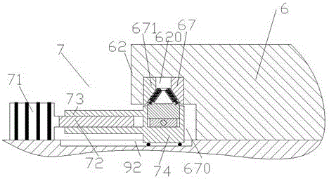
[0015] According to an embodiment of the present invention, a simple floating workbench mechanism includes a base 9 and a workbench 6 capable of floating and moving on the plane of the base 9, and the workbench 6 is provided with a horizontal axis driving device 8 and the vertical axis driving device 7, the horizontal axis driving device 8 includes a horizontal axis motor 81 coupled with the horizontal axis screw rod 82, and the vertical axis driving device 7 includes a vertical axis motor 71 coupled with the vertical axis screw rod 72, wherein, The right side of the workbench 6 is provided with a longitudinally extending protruding portion 61 so as to form a horizontally driving suspension portion 680 between the longitudinally extending protruding portion 61 and the base 9, for placing and threading on the The horizontal push-pull assembly 84 fixedly connected to the horizontal shaft screw...


PUM


Abstract

The invention discloses a simple floating type workbench mechanism which comprises a substrate (9) and a workbench (6) which can float on a plane of the substrate (9); the workbench (6) is provided with a transverse shaft drive device (8) and a longitudinal shaft drive device (7); the transverse shaft drive device (8) is composed of a transverse shaft motor (81) which is coupled with a transverse shaft screw rod (82); the longitudinal shaft drive device (7) is composed of a longitudinal shaft motor (71) which is coupled with a longitudinal shaft screw rod (72); and a longitudinal extension protruding part (61) is arranged on the right side of the workbench (6), so that a suspending part (680) for transverse drive is formed between the longitudinal extension protruding part (61) and the substrate (9).

Description

technical field [0001] The invention relates to the field of workbench adjustment, in particular to a simple floating workbench mechanism. Background technique [0002] Worktables are commonly used components in processing devices. In order to adjust the precise position of the workbench, it is usually adjusted with a dual-axis drive, and one of the two drive assemblies is located inside or above the other to form a master drive and a slave drive, so that the motion is superimposed to complete the position adjustment. This type of adjustment tends to increase the overall weight of the table because the overall weight of the slave drive exists as a load on the master drive. However, it is difficult to form precise position adjustment by using equal adjustment methods. And it is easy to form a gap at the transmission part, thereby affecting the transmission and adjustment accuracy. Contents of the invention [0003] The object of the present invention is to provide a simp...

Claims


Application Information

Patent Timeline
Patent Type & Authority Applications(China)
IPC IPC(8): B23Q1/40B23Q1/62B23Q5/40B23Q5/28
CPCB23Q1/40B23Q1/621B23Q5/28B23Q5/40
Inventor 王启先
Owner 王启先
Why Eureka
Try Eureka