Automatic stamping device

An automatic, official seal technology, applied in printing, stamping and other directions, can solve unrealistic problems and achieve the effect of improving work efficiency

Active Publication Date: 2016-10-12
SUZHOU INST OF TRADE & COMMERCE
View PDF6 Cites 8 Cited by
  • Summary
  • Abstract
  • Description
  • Claims
  • Application Information

AI Technical Summary

Problems solved by technology

Also stamping technology is mainly used in stamping in industrial production, which needs to provide compressed air, but for daily office stamping, it is unrealistic to provide compressed air as power

Method used


Image

  • Automatic stamping device

Examples


Embodiment Construction

[0015] The present invention will be described in detail below with reference to the accompanying drawings and in combination with embodiments.

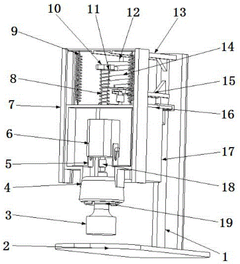
[0016] Such as figure 1 As shown, an automatic stamping device includes a column 1, the column 1 is connected to the bottom plate 2, the top of the column 1 is spliced ​​with the first support beam 13 by welding, and the bottom of the first support beam 13 is provided with The second support beam 15, the third support beam 16 is provided below the second support beam 15, and the second support beam 15 and the third support beam 16 are all spliced ​​with the column 1 by welding, the The first support beam 13 supports the slide rail 7, the second support beam 15 supports the shaft 12 and the cam 14, the pressing motor 17 is suspended and fixed by the third support beam 16, and the slide rail 7 passes through the first The spring 9 is connected with the outer chuck 4, the outer chuck 4 is fixed with a sliding pin 8, the sliding pin 8 i...


PUM


Abstract

The invention discloses an automatic stamping device. The automatic stamping device comprises a vertical column which is connected to a bottom plate, wherein the top end of the vertical column is spliced with a first supporting beam by welding; a second supporting beam is arranged below the first supporting beam; a third supporting beam is arranged below the second supporting beam; the second supporting beam and the third supporting beam are spliced with the vertical column by welding; the first supporting beam is used for supporting a slide rail; the second supporting beam is used for supporting a shaft and a cam; a downward pressing motor is suspended and fixed through the third supporting beam; the slide rail is connected to an outer clamping head through first springs; a slide pin sleeved by a slide sleeve is fixed to the outer clamping head; a second spring sleeves the slide sleeve and the slide pin; and an inner clamping head is mounted in the outer clamp. According to the automatic stamping device, electricity is taken as the power to replace manual stamping, and as a result, the automatic stamping can be realized; and the technical problems such as clamping and replacing of an official seal, automatic mechanical downward pressing during stamping, and adjustable stamping height can be solved. Therefore, stamping workers can be released from the heavy repeating work, and as a result, the working efficiency can be improved.

Description

technical field [0001] The invention relates to an automatic sealing device. Background technique [0002] The existing technical solutions for automatic stamping equipment mainly include the following categories: [0003] 1. Electromagnetic automatic stamping equipment. It is mainly composed of a base, main and auxiliary gears, two gear slots, a rubber conveyor belt connecting the main and auxiliary gears, an electromagnet, a motor, a small robot arm, a robot arm bracket, two single-chip microcomputers for controlling the motor and a small robot arm, and two It consists of a DC power supply, a slidable stage, and related circuits. Use single-chip microcomputer 1 to control the operation and stop of the motor, and use single-chip microcomputer 2 to control the rise and fall of the manipulator through electromagnets. The structure of the technical scheme is relatively complicated, and the sealing action is not high in the adsorption reliability and strength of the electrom...

Claims


Application Information

Patent Timeline
Patent Type & Authority Applications(China)
IPC IPC(8): B41K3/04B41K3/62
CPCB41K3/04B41K3/62
Inventor 王强杨娟
Owner SUZHOU INST OF TRADE & COMMERCE
Why Eureka
Try Eureka