A wire crimping piece bending machine

A wire crimping and bending machine technology, which is applied in the field of bending machines, can solve problems such as direct winding, reverse wire crimping of electric energy meter voltage wires, and failure to put them into the jaws.

Active Publication Date: 2019-10-11
ZHANGQIU POWER SUPPLY CO OF STATE GRID SHANDONG ELECTRIC POWER CO +1
View PDF6 Cites 0 Cited by
  • Summary
  • Abstract
  • Description
  • Claims
  • Application Information

AI Technical Summary

Problems solved by technology

[0002] The high risk and precision of the power system make the use of tools and wiring methods must be safe and reliable. The voltage line of the meter and the low-voltage busbar of the transformer are directly crimped to the upper port of the DW switch or knife switch with screws. Some problems are often encountered in the process: when the nut is crimped to the clamp of the low-voltage line of the transformer, due to the great force, it will cause damage to the voltage line, and the wire will be flattened, resulting in future operation accompanied by AC contactors, etc. The vibration caused by the closing and opening of the switch may cause the broken line at the flattened part
The work of the staff is not standardized, and sometimes the voltage wires of the electric energy meter are crimped against the wire and directly entangled
Directly use nuts to crimp the wires. Generally, workers need to wind the wires on the screw along the wire, and then tighten the nuts along the screw with a wrench. Moreover, the tightening force must be controlled according to the hardness of the wires. The work is cumbersome and time-consuming.
[0003] Nowadays, a wire crimping piece consisting of a bolt crimping hole and a crimping sleeve plate stamped by a copper plate is generally used, but the crimping sleeve plate of the stamped crimping piece is generally a flat plate, and it is generally used in the field. The width of the crimping sleeve is too large to fit into the jaws, or it is bent in the opposite direction to the wire during crimping, which delays working time. Now it is necessary to bend the crimping sleeve of the wire crimping piece in advance to ensure on-site convenience use

Method used


Image

  • A wire crimping piece bending machine
  • A wire crimping piece bending machine
  • A wire crimping piece bending machine

Examples


Embodiment Construction

[0024] In order to better understand the present invention, the specific implementation manners of the present invention will be explained in detail below in conjunction with the accompanying drawings.

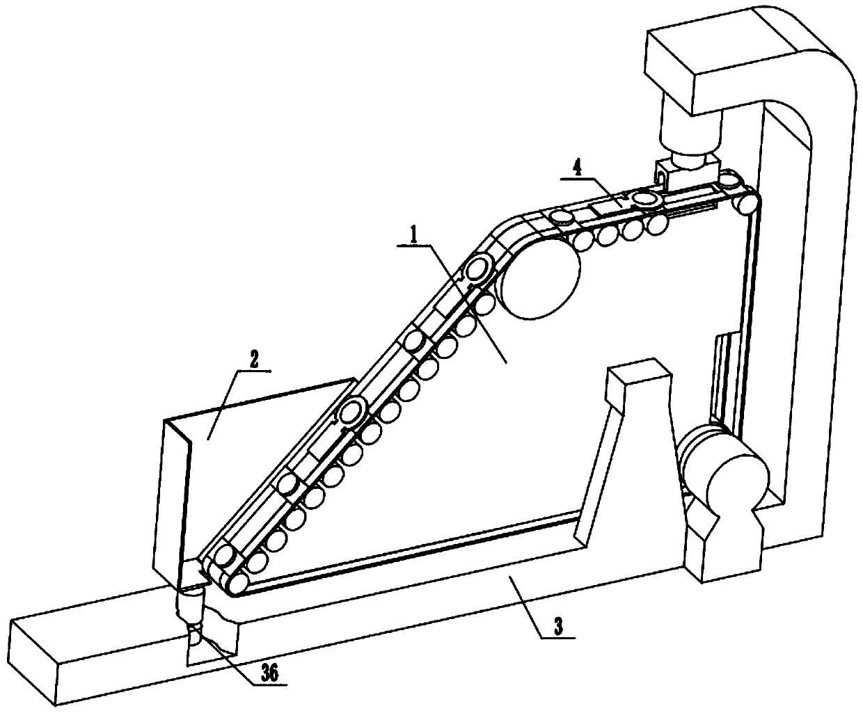
[0025] A bending machine for wire crimping parts, including a conveying mechanism 1, a hopper 2, a bracket 3, and a wire crimping part 4. The wire crimping part 4 is a part to be punched, and the conveying mechanism 1 is fixed on the bracket through a fixing frame 31 3, the hopper 2 is installed on the support 3 through a vibrator 36, and the vibrator 36 is generally driven by hydraulic pressure or air pressure, and can be driven by an electric motor.

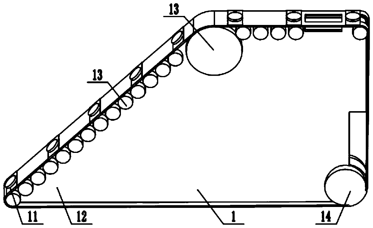
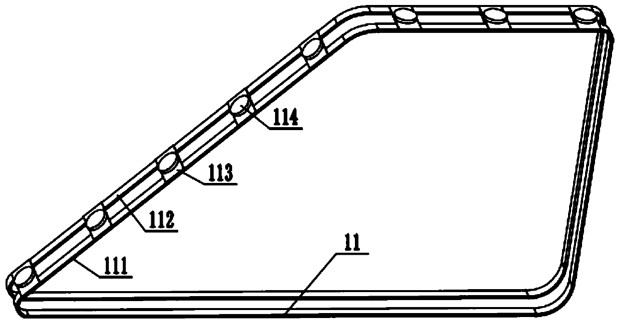
[0026] Described conveying mechanism 1 comprises conveyor belt 11, support member 12, support roller 13, and support member 12 comprises support plate 121, driving friction wheel 14, and support plate 121 is a trapezoidal plate, and generally used support plate 121 is a right-angled trapezoidal plate; Plate 121 includes guide r...


PUM


Abstract

The invention discloses a conducting wire compression joint component bending machine which comprises a conveying mechanism and the like. The conveying mechanism is fixed onto a support by the aid ofa fixing frame, a hopper is mounted on the support via a vibrator, the conveying mechanism comprises a conveyor belt and a support component, the support component comprises a support plate, roll shaft holes are formed in a middle line edge and a top line edge of the support plate, support rolls are arranged on the support plate via the roll shaft holes, the axes of the support rolls are perpendicular to planes of the support plate, the support rolls are arranged on two sides of the support plate, a driving friction wheel is arranged at an edge of the support plate, and the conveyor belt is arranged on the support component and can be tensioned by the support rolls and the driving friction wheel; a motor is arranged on the support and is connected with the driving friction wheel in a driving manner. The conducting wire compression joint component bending machine has the advantages that the problems of inconvenience in manual operation and long time consumption due to large quantities of small components can be solved by the aid of the conducting wire compression joint component bending machine; the conducting wire compression joint component bending machine is provided with automatic feeding, automatic loading and automatic stamping devices, accordingly, manual intervention can be omitted, and conducting wire compression joint components only need to be placed in the hopper andcan be automatically stamped by the conducting wire compression joint component bending machine.

Description

technical field [0001] The invention relates to the field of electrical equipment, in particular to a small bending machine for automatic feeding and quick bending of wire crimping parts. Background technique [0002] The high risk and precision of the power system make the use of tools and wiring methods must be safe and reliable. The voltage line of the meter and the low-voltage busbar of the transformer are directly crimped to the upper port of the DW switch or knife switch with screws. Some problems are often encountered in the process: when the nut is crimped to the clamp of the low-voltage line of the transformer, due to the great force, it will cause damage to the voltage line, and the wire will be flattened, resulting in future operation accompanied by AC contactors, etc. The vibration caused by the closing and opening of the switch may cause the broken line at the flattened part. The work of the staff is not standardized, and sometimes the voltage wire of the elect...

Claims


Application Information

Patent Timeline
Patent Type & Authority Patents(China)
IPC IPC(8): B21D22/02B21D37/10B21D43/06B21D43/12B21D43/00B21C51/00
Inventor 刘振华孟钢程旭赵利强李毅刘冠东贾虎隗永牛磊贺可栋
Owner ZHANGQIU POWER SUPPLY CO OF STATE GRID SHANDONG ELECTRIC POWER CO
Why Eureka
Try Eureka