Balance vehicle wheel fixing structure and balance vehicle

A technology of fixed structure and balance car, applied in the direction of motor vehicles, bicycles, two-wheeled bicycles, etc., can solve the problems of occupying space, easy movement, easy rolling of wheels, etc., and achieve the effect of small space occupation

Active Publication Date: 2016-10-12
深圳市骜途智能科技有限公司
5 Cites 7 Cited by

AI-Extracted Technical Summary

Problems solved by technology

[0004] Existing self-balancing vehicles occupy a lot of space, and need to occupy a large space when not in use
A...

Abstract

The invention discloses a balance vehicle wheel fixing structure and a balance vehicle. The balance vehicle wheel fixing structure comprises a hollow pipe body; a movable shaft and a first clamping buckle are arranged in the hollow pipe body in a sleeving manner; a wheel axle of a wheel can be arranged in the hollow pipe body in a sleeving manner; one end of the movable shaft is movably connected with the wheel axle; the other end of the movable shaft is fixed to the first clamping buckle in a matched manner when the wheel axle is accommodated in the hollow pipe body; a second clamping buckle which is fixed to the side wall of the wheel axle in the matched manner at the opening of the hollow pipe body when the wheel is folded. According to the balance vehicle wheel fixing structure and the balance vehicle, wheels can be folded; the structure is simple; the occupied space is small.

Application Domain

Technology Topic

Image

  • Balance vehicle wheel fixing structure and balance vehicle
  • Balance vehicle wheel fixing structure and balance vehicle
  • Balance vehicle wheel fixing structure and balance vehicle

Examples

  • Experimental program(1)

Example Embodiment

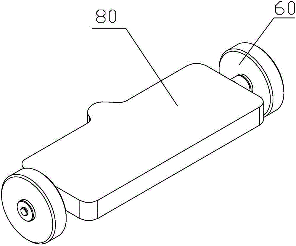
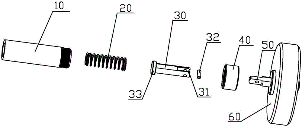
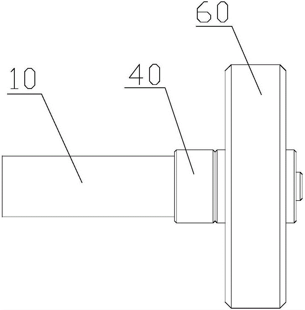
[0031] The invention discloses a balance car. The balance car includes a car body; the car body is provided with a wheel fixing structure. The wheel fixing structure includes a hollow tube body; the hollow tube body is sleeved with a movable shaft and a first buckle; the wheel shaft of the wheel can be sleeved into the hollow tube body; one end of the movable shaft is movably connected with the wheel shaft, and the other end is on the wheel shaft When stored in the hollow tube body, it is matched and fixed with the first buckle; the opening of the hollow tube body is provided with a second buckle which is matched and fixed with the side wall of the wheel axle when the wheel is folded.
[0032] The invention utilizes the cooperation of the hollow tube body, the movable shaft, the first buckle and the second buckle to realize the folding of the wheels of the balance vehicle. In normal use, the rotating axle is parallel to the movable axle. The movable axle and the axle can be embedded in the hollow tube and positioned by the first buckle to prevent sliding in the horizontal position. At this time, the tire is perpendicular to the hollow tube, which is a normal driving state. When folding the wheel, pull the wheel to expose the hollow tube body completely, and then turn to the wheel shaft so that it is perpendicular to the movable shaft. At this time, the wheel is parallel to the hollow tube body and is in a folded state. By cooperating with the second buckle, the wheel axle is locked and positioned at the opening of the hollow tube body to maintain the folded state of the wheel. In addition, the entire folding structure can be accommodated in the hollow tube body, with a very small space occupation, and can be applied to balance cars of different styles.
[0033] In the description of the present invention, it should be understood that the terms "center", "lateral", "upper", "lower", "left", "right", "vertical", "horizontal", "top", The orientation or positional relationship indicated by "bottom", "inner", "outer", etc. are based on the orientation or positional relationship shown in the drawings, which is only for the convenience of describing the present invention and simplifying the description, and does not indicate or imply the pointed device Or the element must have a specific orientation, be constructed and operated in a specific orientation, and therefore cannot be understood as a limitation of the present invention. In addition, the terms "first" and "second" are only used for descriptive purposes, and cannot be understood as indicating or implying relative importance or implicitly indicating the number of indicated technical features. Thus, the features defined with "first" and "second" may explicitly or implicitly include one or more of these features. In the description of the present invention, unless otherwise specified, "plurality" means two or more. In addition, the term "including" and any variations thereof is intended to cover non-exclusive inclusion.
[0034] In the description of the present invention, it should be noted that the terms "installation", "connected" and "connected" should be understood in a broad sense, unless otherwise clearly specified and limited. For example, they can be fixed or detachable. Connected or integrally connected; it can be a mechanical connection or an electrical connection; it can be directly connected or indirectly connected through an intermediate medium, and it can be the internal communication between two components. For those of ordinary skill in the art, the specific meanings of the above-mentioned terms in the present invention can be understood in specific situations.
[0035] The terminology used here is only for describing specific embodiments and is not intended to limit the exemplary embodiments. Unless the context clearly dictates otherwise, the singular forms "a" and "one" used herein are also intended to include the plural. It should also be understood that the terms "including" and/or "comprising" used herein specify the existence of the stated features, integers, steps, operations, units and/or components, and do not exclude the existence or addition of one or more Other features, integers, steps, operations, units, components, and/or combinations thereof.
[0036] The following combination Figure 1-12 The concept of the present invention is further explained.
[0037] This embodiment discloses a balance vehicle, which includes a vehicle body; the vehicle body is provided with a wheel fixing structure. The wheel fixing structure includes a hollow tube body; the hollow tube body is sleeved with a movable shaft and a first buckle; the wheel shaft of the wheel can be sleeved into the hollow tube body; one end of the movable shaft is movably connected with the wheel shaft, and the other end is on the wheel shaft When stored in the hollow tube body, it is matched and fixed with the first buckle; the opening of the hollow tube body is provided with a second buckle which is matched and fixed with the side wall of the wheel axle when the wheel is folded. The buckle should be understood in a broad sense, and the conventional latch, circlip and other structures that can be used to fix the buckle should fall within the scope of the buckle of the present invention.
[0038] Optionally, a cap sleeve is sleeved at the opening of the hollow tube body; the aperture of the cap sleeve is smaller than the inner diameter of the hollow tube opening; the second snap is fixed on the cap sleeve. The cap sleeve is fixed at the opening of the hollow tube body by threads. The cap cover can facilitate the disassembly and assembly of the movable shaft and the wheel shaft.
[0039] The inner top surface and the bottom surface of the cap sleeve are both flat surfaces; correspondingly, the upper surface and the lower surface of the movable shaft are also flat surfaces, which cooperate with the inner top surface and the bottom surface of the cap sleeve to form a limit structure that restricts the rotation of the movable shaft. The inner diameter shape of the cap sleeve is used to limit the movable shaft to prevent the rotating shaft from rotating, so that there is no need to set a limit structure in the hollow tube, and the production cost is reduced.
[0040] The length of the axle is greater than the caliber of the cap sleeve. In this way, when the rotating shaft is perpendicular to the cap sleeve, that is, when the wheel is folded, the second buckle is clamped at the cap sleeve opening at the cap sleeve opening to realize automatic positioning.
[0041] The fixed end of the movable shaft and the wheel shaft is provided with a groove; the two inner walls of the groove are provided with a rotating shaft; correspondingly, the wheel shaft is embedded in the groove; the wheel shaft is provided with a through hole for the rotating shaft; When the wheel shaft rotates parallel to the movable shaft, the rotating shaft can be embedded in the hollow tube together with the movable shaft; when the rotating shaft rotates perpendicular to the movable shaft, the rotating shaft is fixed at the opening of the cap sleeve through the second buckle.
[0042] The wheel shaft includes a fixed part that is matched with the groove and a base connected to the fixed part; the end surface of the movable shaft at one end of the groove is a concave arc surface; the connection between the base and the fixed part is provided with a concave Convex curved surface adapted to the curved surface. The curved surface helps reduce friction when rotating the axle.
[0043] A disc is connected to the opposite end of the movable shaft and the wheel shaft; the outer diameter of the disc is consistent with the inner diameter of the hollow tube.
[0044] Optionally, the present invention does not necessarily require a cap, and it is also feasible to directly form a positioning structure of the spring and the movable shaft inside the hollow tube. This has fewer parts and a more compact structure. Specifically, the hollow tube body adopts a non-circular structure inside, which can be elliptical, rectangular, etc., of course, the top and bottom surfaces of the interior can also be flat; correspondingly, the upper and lower surfaces of the movable shaft are also flat. Cooperating with the inner top surface and bottom surface of the hollow tube body to form a limit structure that limits the rotation of the movable shaft. At this time, the length of the axle is greater than the inner diameter of the hollow tube body. The movable shaft, wheel shaft and other structures can refer to the previous description, and will not be repeated here.
[0045] Compared with the prior art, the technical effect of the present invention is that the present invention utilizes the cooperation of the hollow tube body, the movable shaft, the first buckle and the second buckle to realize the folding of the wheel of the balance vehicle. In normal use, the rotating axle is parallel to the movable axle. The movable axle and the axle can be embedded in the hollow tube and positioned by the first buckle to prevent sliding in the horizontal position. At this time, the tire is perpendicular to the hollow tube, which is a normal driving state. When folding the wheel, pull the wheel to expose the hollow tube body completely, and then turn to the wheel shaft so that it is perpendicular to the movable shaft. At this time, the wheel is parallel to the hollow tube body and is in a folded state. By cooperating with the second buckle, the wheel axle is locked and positioned at the opening of the hollow tube body to maintain the folded state of the wheel. In addition, the entire folding structure can be accommodated in the hollow tube body, with a very small space occupation, and can be applied to balance cars of different styles.
[0046] The above content is a further detailed description of the present invention in conjunction with specific preferred embodiments, and it cannot be considered that the specific implementation of the present invention is limited to these descriptions. For those of ordinary skill in the technical field to which the present invention belongs, a number of simple deductions or substitutions can be made without departing from the concept of the present invention, which should be regarded as falling within the protection scope of the present invention.

PUM

no PUM

Description & Claims & Application Information

We can also present the details of the Description, Claims and Application information to help users get a comprehensive understanding of the technical details of the patent, such as background art, summary of invention, brief description of drawings, description of embodiments, and other original content. On the other hand, users can also determine the specific scope of protection of the technology through the list of claims; as well as understand the changes in the life cycle of the technology with the presentation of the patent timeline. Login to view more.

Similar technology patents

Air conditioner indoor unit

ActiveCN108426303AReduce space consumptionSolve the problem of taking up a lot of spaceEnergy recovery in ventilation and heatingMechanical apparatusEngineeringAir conditioning
Owner:QINGDAO HAIER AIR CONDITIONER GENERAL CORP LTD +2

Optical power automatic calibration system and method

InactiveCN111103055AReduce manual adjustment timeReduce space consumptionPhotometry electrical circuitsOptical powerLight source
Owner:上海传输线研究所

Packaging barrel lifting and moving mechanism

Owner:东营金慧科技咨询有限公司

Classification and recommendation of technical efficacy words

Why Eureka
Try Eureka