Testing device for directly measuring jet-flow thrust

A test device and jet technology, which is used in measurement devices, aerodynamic tests, machine/structural component testing, etc. effect of small length

Active Publication Date: 2017-06-13
CHINA ACAD OF AEROSPACE AERODYNAMICS
View PDF5 Cites 24 Cited by
  • Summary
  • Abstract
  • Description
  • Claims
  • Application Information

AI Technical Summary

Problems solved by technology

[0004] In the conventional jet flow test, the influence of the jet flow and the aerodynamic force of the whole machine can be obtained by performing different tests with a single six-component balance, but there are errors caused by a large amount of reduction in data processing, which reduces the test accuracy

Method used


Image

  • Testing device for directly measuring jet-flow thrust

Examples


Embodiment Construction

[0029] The present invention will be further described in detail below in conjunction with the accompanying drawings.

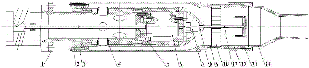
[0030] The function of the jet thrust test device is to guide the high-pressure gas introduced by the central ventilation rod to the nozzle. The jet thrust test device is divided into a fixed part and a floating part. The central ventilation straight rod is the fixed part of the device, and the compressed air is ventilated from the center. The straight rod enters the jet flow device, and the nozzles are arranged at equal intervals radially in the two sections of the rear section. The floating part includes the annular ventilation pipeline, the front chamber of the nozzle, the rectifying honeycomb and the tail nozzle and other parts. The six-component thrust vector balance / sensor is connected between the floating part and the fixed part, which is used to measure the reaction force after the jet flow in the nozzle is turned. The gap between the chamber and the...


PUM


Abstract

Provided is a testing device for directly measuring jet-flow thrust. The device includes a central ventilation support rod, a ripple tube, a casing, small jet nozzles, a thrust vector scale/sensor, a fairing cone, an outer tube, a fairing plate, a transition section and an exhaust nozzle; the front end of the central ventilation support rod is fixedly connected with an external ventilation support device, ventilation holes are uniformly formed in the central ventilation support rod in the circumferential direction, the back end of the central ventilation support rod is connected with a fixed end of the thrust vector scale/sensor, the exterior of the central ventilation support rod is sequentially sleeved with the ripple tube and the casing, ventilation holes are uniformly formed in the ripple tube and the casing in the circumferential direction, the positions of the ventilation holes in the ripple tube and the casing accord with the positions of the ventilation holes in the central ventilation support rod, the ventilation holes at the same positions are communicated through the small jet nozzles, the front end of the ripple tube and the front the of the casing are fixedly connected with the outer tube, the back end of the ripple tube is connected with a floating end of the thrust vector scale/sensor and fixedly connected with the back end of the casing, the fairing cone is connected to the back end of the ripple tube in a sleeved mode, the outer tube and the exhaust nozzle are connected through the transition section, and the fairing plate is installed between the outer tube and the transition section and located in front of a contraction section of the exhaust nozzle.

Description

technical field [0001] The invention relates to a test device for directly measuring jet thrust in a wind tunnel, and belongs to the technical field of aerospace aerodynamic test structures. Background technique [0002] The thrust vectoring technology of the aircraft can turn part of the engine thrust into the control force, replacing or partially replacing the control surface, thereby greatly reducing the radar reflection area; no matter how large the angle of attack is and how low the flight speed is, the aircraft can use this part of the control force to perform maneuvering, which increases the maneuverability of the aircraft. [0003] When the aircraft thrust turns, on the one hand, it provides a direct change of the thrust direction, on the other hand, the change of the jet flow direction also changes the flow of the airflow around the aircraft, so it also has an important impact on the aerodynamic force of the aircraft. This effect must be taken into account when det...

Claims


Application Information

Patent Timeline
Patent Type & Authority Applications(China)
IPC IPC(8): G01M9/06G01M9/04
CPCG01M9/04G01M9/06
Inventor 郑芳贾毅尹世博
Owner CHINA ACAD OF AEROSPACE AERODYNAMICS
Why Eureka
Try Eureka