Synchronous clamping mechanism

A technology of synchronous clamping and fixing blocks, which is applied in the direction of auxiliary devices, auxiliary welding equipment, welding/cutting auxiliary equipment, etc., can solve the problems of inability to meet strict requirements, expensive cylinders, and difficult mechanisms, and achieve low cost, The effect of simple structure and less space occupation

Active Publication Date: 2010-08-11
ANHUI JEE AUTOMATION EQUIP CO LTD
View PDF0 Cites 26 Cited by
  • Summary
  • Abstract
  • Description
  • Claims
  • Application Information

AI Technical Summary

Problems solved by technology

At the same time, due to the high price of the cylinder, the cost is high
[0003] However, for some positions, due to the limitation of space, it is difficult or impossible for the above mechanism to achieve its strict requirements, and sometimes it is required to clamp two positions at the same time

Method used


Image

  • Synchronous clamping mechanism
  • Synchronous clamping mechanism
  • Synchronous clamping mechanism

Examples


Embodiment Construction

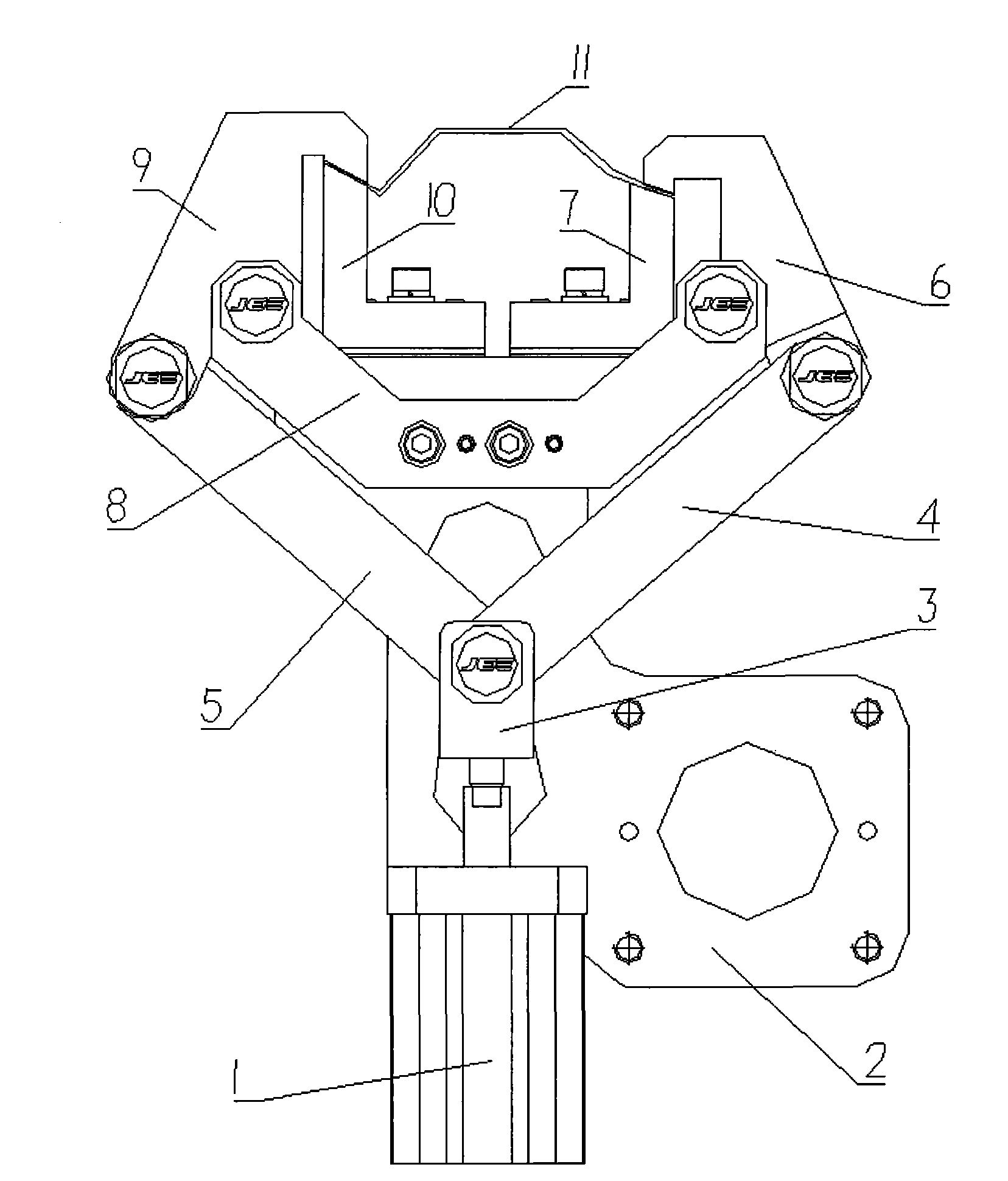
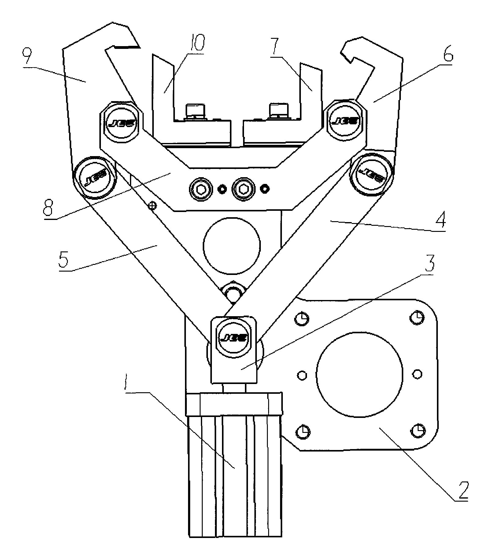
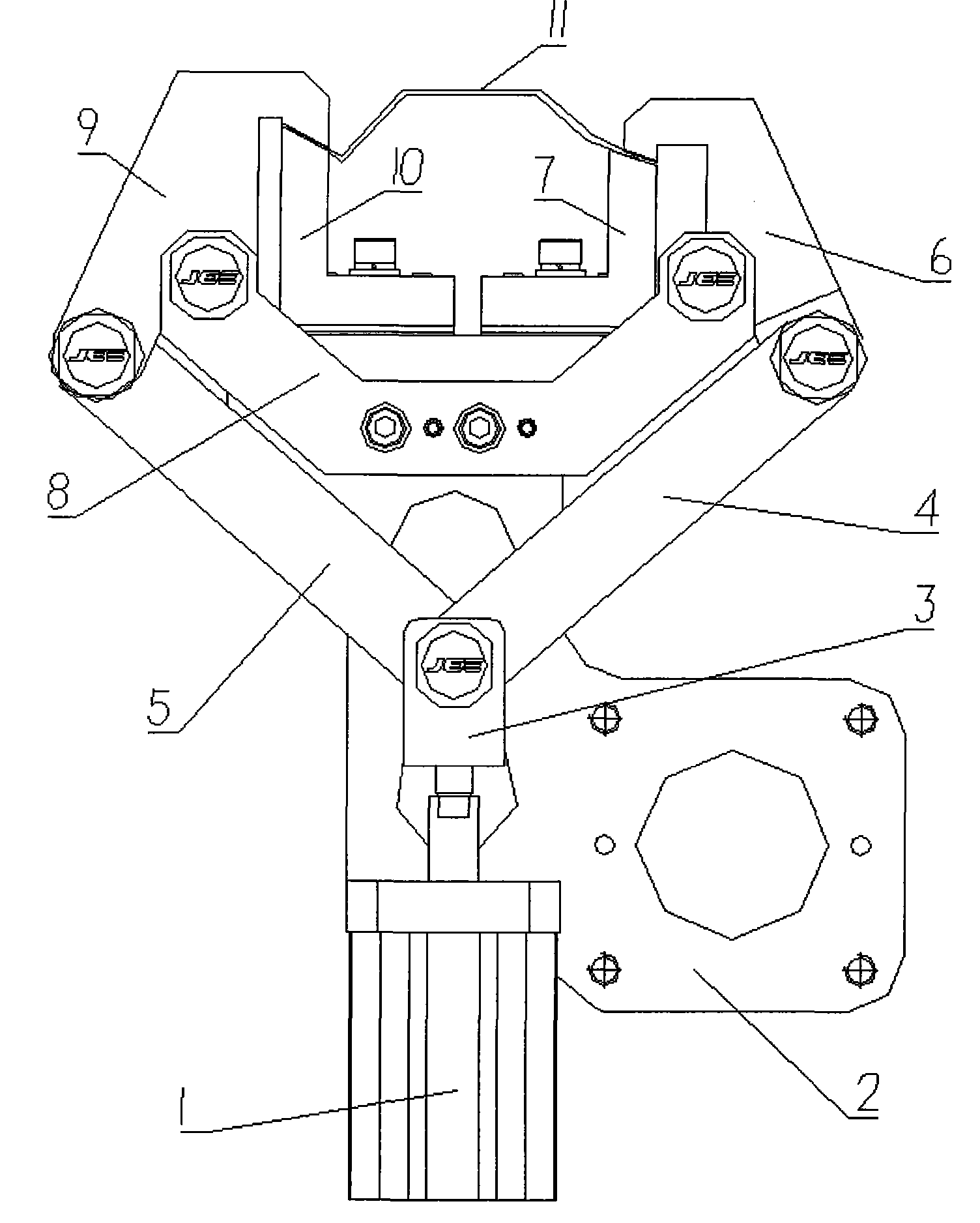
[0018] see figure 1 , with the cylinder 1 as the driving part, the rod end of the cylinder piston rod passes through the joint 3 to form a "Y" symmetrical hinged left connecting rod 5 and the right connecting rod 4, and the rod ends of the left connecting rod 5 and the right connecting rod 4 respectively pass through The rotating shaft hinges the left half claw 9 and the right half claw 6, and the left half claw 9 and the right half claw 6 are symmetrically arranged on the left and right. The waists of the claws are respectively hooked on symmetrically arranged fixed rotating shafts, and can rotate around the fixed rotating shafts.

[0019] In specific implementation, "V" shaped fixed block 8 is set, and the fixed rotating shaft is the left and right two tops of "V" shaped fixed block 8; "V" shaped fixed block 8 is fixedly arranged on the fixed pattern plate 2; The type fixed block 8 is enveloped between the left connecting rod 5 and the right connecting rod 4 arranged in a "...


PUM


Abstract

The invention discloses a synchronous clamping mechanism, which is characterized in that an air cylinder is taken as a driving piece; the rod end of an air cylinder piston rod is symmetrically hinged with a left connecting rod and a right connecting rod in a 'Y' shape through a joint; rod ends of the left connecting rod and the right connecting rod are hinged with a left half claw and a right half claw through a rotating shaft respectively; the left half claw and the right half claw are in the bilaterally-symmetric arrangement; head parts of the left and the right claws can be buckled on a left clamping block and a right clamping block inwards respectively; and waists of the left and the right claws are hung on fixed rotating shafts symmetrically arranged respectively and can rotate around the fixed rotating shafts. In the synchronous clamping mechanism, the air cylinder is taken as power, the connecting rods are utilized to realize transmission of power, and the synchronous action of the mechanism can be achieved without utilizing other auxiliary elements such as electrics and the like to perform feedback; and the synchronous clamping mechanism has the advantages of reliable operation and little space occupation, and is suitable for occasions where space requirements are harsh.

Description

technical field [0001] The invention relates to a synchronous clamping mechanism, more specifically, a mechanism that is driven by a cylinder and utilizes a link mechanism to realize synchronous clamping at two positions in space. It is especially suitable for use in occasions where the space range is limited. Background technique [0002] In the field of automobile welding, it is often used to clamp the position that needs to be clamped by relying on the cylinder as the power. At present, the clamping cylinder clamping unit of SMC and FESTO is used more to clamp the position that needs to be clamped. , and use the TUNKERS integrated clamping cylinder to clamp the position that needs to be clamped. Using the clamping cylinder of SMC and FESTO to make the connecting rod mechanism for clamping unit requires a large open space. When the cylinder drives the connecting rod to move, a large open space is required. The unit that uses the TUNKERS integrated clamping cylinder to cl...

Claims


Application Information

Patent Timeline
Patent Type & Authority Applications(China)
IPC IPC(8): B23K37/04
Inventor 林巨广牛赵龙胡育松韩慧柏龙驭施成攀储大飞李彪
Owner ANHUI JEE AUTOMATION EQUIP CO LTD
Why Eureka
Try Eureka