
Continuous multi-unit single meter splitting machine

A technology of meter machine and unit order, which is applied in the field of continuous multi-unit order sorting machine, which can solve the problems that multi-unit orders cannot be automatically divided into single-unit orders, etc., and achieve the effect of stable operation and high efficiency of order sorting

Inactive Publication Date: 2017-11-17
北京赛德曼兴业科技有限公司
View PDF1 Cites 0 Cited by
  • Summary
  • Abstract
  • Description
  • Claims
  • Application Information

AI Technical Summary

Problems solved by technology

[0005] The purpose of the present invention is to provide a continuous multi-part sheet sorting machine to solve the problem that the existing multi-part sheets cannot be automatically divided into single-part sheets

Method used


Image

  • Continuous multi-unit single meter splitting machine
  • Continuous multi-unit single meter splitting machine
  • Continuous multi-unit single meter splitting machine

Examples


Embodiment 1

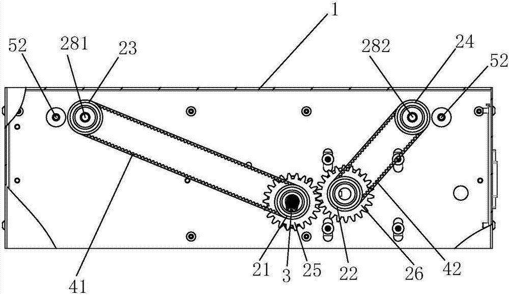
[0026] This embodiment provides a continuous multi-connected single meter splitter, the motor is assembled and connected to the inside of the chassis 1, and the driving wheel 21, the first driven wheel 22, the second driven wheel 23 and the third driven wheel 24 are hinged to the chassis 1 through bearings Inside, the output shaft 3 of the motor is assembled and connected to the driving wheel 21, the first gear 25 is assembled and connected to the driving wheel 21, the second gear 26 is assembled and connected to the first driven wheel 22, the first gear 25 meshes with the second gear 26, and the driving wheel 21 Connect the second driven wheel 23 through the first conveyor belt 41, the first driven wheel 22 connects the third driven wheel 24 through the second conveyor belt 42, the second driven wheel 23 and the third driven wheel 24 are all assembled to connect the paper clip wheel 27; The assembly includes two first transmission shafts 51 and two second transmission shafts 5...

Embodiment 2

[0028] The difference between this embodiment and Embodiment 1 is that the second driven wheel 23 is assembled and connected with the first connecting shaft 281, the two ends of the first connecting shaft 281 are assembled and connected with the paper clamping wheel 27, and the third driven wheel 24 is assembled and connected with the second The connecting shaft 282 and the two ends of the second connecting shaft 282 are assembled to connect the clamping wheel 27 . In this way, the clamping wheel 27 on one side engages the two ends of the first joint 621 and drives the first joint 621 to move to the left side of the chassis 1 smoothly, and the paper clamping wheel 27 on the other side engages the two ends of the second joint 622. end and drives the second joint 622 to move to the right side of the chassis 1 smoothly. This makes the single operation run more smoothly.

Embodiment 3

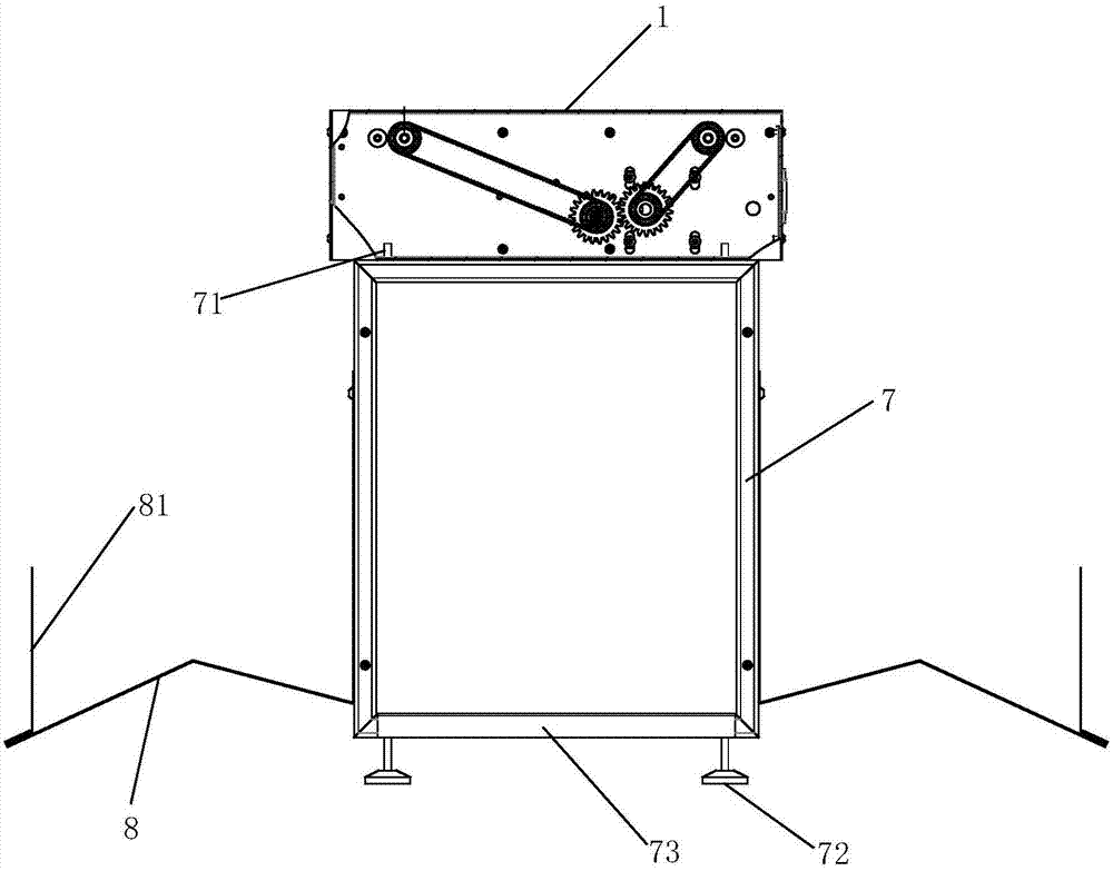
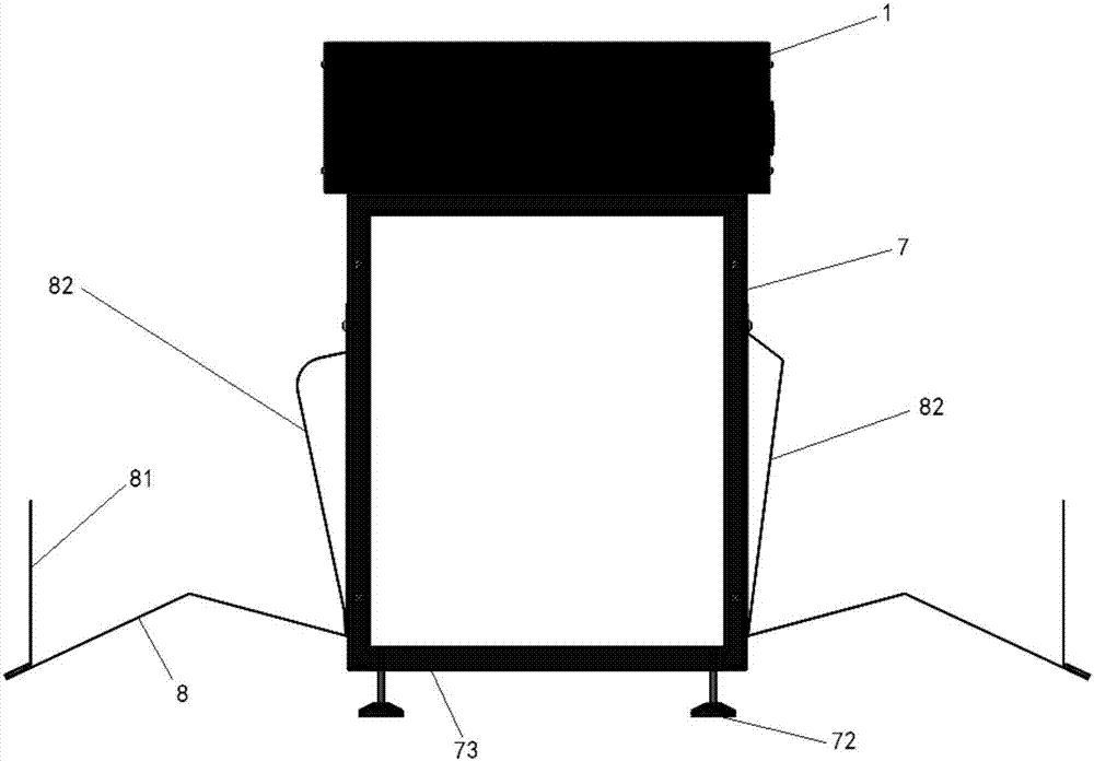
[0030] The difference between this embodiment and Embodiment 2 is that it also includes a frame 7, the upper part of the frame 7 is fixedly connected with a connecting pin 71, and the lower part of the chassis 1 is provided with a connecting hole that can be engaged with the connecting pin 71, so that The continuous multi-unit single-distributing machine in this embodiment is convenient for disassembly and assembly, and is convenient for logistics and transportation. The lower part of the frame 7 is fixedly connected with an anchor 72 to support the frame 7 more stably. The bottom of the frame 7 is fixedly connected with a paper holder 73, on which the folded multiple sheets 61 can be placed.


PUM


Abstract

The invention discloses a continuous delivering machine for a bill in multiple parts. A motor is assembled and connected to the interior of a case. A driving wheel, a first driven wheel, a second driven wheel and a third driven wheel are hinged to the interior of the case. An output shaft of the motor is assembled and connected with the driving wheel. A first gear is assembled and connected with the driving wheel. A second gear is assembled and connected with the first driven wheel. The first gear is meshed with the second gear. The driving wheel is connected with the second driven wheel by virtue of a first conveyor belt. The first driven wheel is connected with the third driven wheel by virtue of a second conveyor belt. The second driven wheel and the third driven wheel are assembled and connected with paper clamping wheels. Two first driving shafts are positioned in the middle of the case and are hinged to the case. Two second driving shafts are separately positioned on two side edges of the case and are hinged to the case. The continuous delivering machine has the beneficial effects that the bill in multiple parts can be automatically divided into a bill in a single part, operation is stable, and the bill delivering efficiency is high.

Description

technical field [0001] The invention relates to the technical field of automatic office equipment, in particular to a continuous multi-connected single-distributor. Background technique [0002] Enterprises and institutions need a large number of financial non-tax vouchers, invoices and circulation documents in their operations, and most of the above-mentioned vouchers are multiple documents. In practical applications, it is necessary to use a printer to print the content on multiple sheets at one time, and then perform procedures such as binding or distribution separately according to the purpose of each sheet. For many years, multiple orders have been separated manually, which is labor-intensive and inefficient. [0003] The patent document with the patent number CN203624627U discloses a paper feeding mechanism of a document scanning identification classification device, which successively includes a paper feeding solenoid valve, a paper feeding box, a pickup wheel, a fri...

Claims


Application Information

Patent Timeline
Patent Type & Authority Patents(China)
IPC IPC(8): B65H3/06
CPCB65H3/0669
Inventor 高晨辰
Owner 北京赛德曼兴业科技有限公司
Learn More