Eureka AIR delivers breakthrough ideas for toughest innovation challenges, trusted by R&D personnel around the world.

Ultraviolet light disinfection water tank with warning function

A technology of ultraviolet light and water tank, which is applied in the direction of illumination water/sewage treatment, water supply device, configuration of water supply pool, etc., can solve the problems of affecting water quality, increasing water flow resistance, increasing pipeline length, etc., to improve sterilization efficiency and sterilization. effect, the effect of reducing the length of the pipeline

Inactive Publication Date: 2016-10-12
SUZHOU COOBOS FLUID TECH
View PDF4 Cites 0 Cited by
  • Summary
  • Abstract
  • Description
  • Claims
  • Application Information

AI Technical Summary

Problems solved by technology

[0002] For secondary water supply, the traditional water tank is generally only used as an ordinary container with water storage function, with a single function
[0003] However, the existing water tanks are equipped with ultraviolet light disinfection. Usually, the ultraviolet light disinfection device is installed on the outside of the water tank in the form of a side pipe, which is separated from the water tank. Resistance, and the attachment of ultraviolet light tubes and other accessories in the bypass tube will also increase the water flow resistance. This disinfection method is to instantly kill bacteria that flow through tap water quickly, so high-power ultraviolet light tubes are required, and the cost is relatively high.
[0004] Moreover, once the existing ultraviolet light disinfection device has a problem in the use process and cannot be used normally, the staff cannot find it in time, resulting in the failure of the ultraviolet light disinfection to be carried out normally and affecting the water quality.

Method used


Image

  • Ultraviolet light disinfection water tank with warning function

Examples


Embodiment

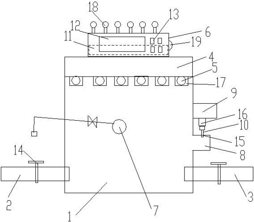
[0019] Embodiment: a kind of ultraviolet disinfection water tank with warning function, comprising a water tank body 1, the water tank body is provided with a water inlet pipe 2 and a water outlet pipe 3, the water tank body is open, and the top of the water tank body is fixed There is a cover plate 4, a number of ultraviolet light tubes 5 are installed on the lower end of the cover plate, a control box 6 is installed on the upper end of the cover plate, a float valve 7 is installed in the water tank body, the side wall of the water tank body An overflow tank 8 is provided on the top, and the overflow tank is connected with the water tank body. A water quality detector 9 is installed above the overflow tank. The detection head 10 of the water quality detector is stretched up and down and inserted in the overflow tank. , the ultraviolet light tube, the water quality detector and the float valve are all communicated with the control box;

[0020] The upper end of described contr...


PUM


Abstract

The invention discloses an ultraviolet light disinfection water tank with a warning function. The ultraviolet light disinfection water tank comprises an open water tank body, wherein a water inlet pipe and a water outlet pipe are arranged on the water tank body; a cover plate is fixed at the top of the water tank body; a plurality of ultraviolet lamp tubes are mounted at the lower end of the cover plate; a control box is mounted at the upper end of the cover plate; a float valve is mounted in the water tank body; an overflow trough is arranged on the side wall of the water tank body and communicated with the water tank body; a water quality detector is mounted above the overflow trough, and a detection head of the water quality detector is inserted in the overflow trough in a vertical stretching and retracting manner; the ultraviolet lamp tubes, the water quality detector and the float valve are all in communication connection with the control box; a plurality of warning lamps are mounted at the upper end of the control box and in communication connection with the control box, and the quantity of the warning lamps is equal to that of the ultraviolet lamp tubes; each ultraviolet lamp tube is equipped with one warning lamp; a voice alarm is mounted on the side wall of the control box and in communication connection with the control box.

Description

technical field [0001] The invention relates to a water tank, in particular to an ultraviolet light disinfection water tank with a warning function. Background technique [0002] For secondary water supply, the traditional water tank is generally only used as an ordinary container with water storage function, and has a single function. If you need to add ultraviolet light disinfection, you generally need to add a special ultraviolet light sterilizer. [0003] However, the existing water tanks are equipped with ultraviolet light disinfection. Usually, the ultraviolet light disinfection device is installed on the outside of the water tank in the form of a side pipe, which is separated from the water tank. Resistance, and the attachment of ultraviolet lamps and other accessories in the bypass pipe will also increase the water flow resistance. This disinfection method is to instantly kill bacteria flowing through tap water, so high-power ultraviolet lamps are required, and the ...

Claims


Application Information

Patent Timeline
Patent Type & Authority Applications(China)
IPC IPC(8): C02F1/32E03B11/00
CPCC02F1/32C02F2201/3227C02F2201/326C02F2303/04E03B11/00
Inventor 朱洪斌周晓斌
Owner SUZHOU COOBOS FLUID TECH
Why Eureka
Eureka Blog
Learn More