Vehicle travelling boundary inducing rod for low-visibility road

A technology for vehicle driving and low visibility, applied to roads, roads, road signs, etc., can solve the problems of small area of ​​retroreflective materials, poor induction performance, poor reflection effect, etc., to eliminate potential safety hazards, increase luminous area, and use costs low effect

Inactive Publication Date: 2016-10-12
新疆交通科学研究院有限责任公司
View PDF10 Cites 1 Cited by
  • Summary
  • Abstract
  • Description
  • Claims
  • Application Information

AI Technical Summary

Benefits of technology

This patented technology describes an improved way that guides vehicles during their route from roads without being visible through obstacles like signs or lights. These guiding parts are made up of lamps attached around its edges instead of just above them themselves. They have increased visibility compared to traditional methods while still providing good signal identification capabilities. Additionally, they don't require expensive components such as LEDs or batteries, making installation easier and faster than previous designs. Overall, this new design improves efficiency and reduces costs by enhancing visualization and sensory perception when navigating over difficult terrain.

Problems solved by technology

This patented technical solution described in this patents involves different types of lights that have been developed over time but they all suffer from certain drawbacks such as being bulky, requiring installation at specific locations within streets where there may be multiple lanes intersecting each other (such as intersections), causing potential collisions between cars during lane changes due to glare caused by reflected light signals when passing through these intersection points, making it difficult to maintain them continuously without frequent replacements. Additionally, current designs use columns made up mostly of circular rectangles instead of square corners, leading to reduced sensitivity towards rain compared to regular highway signage systems.

Method used


Image

  • Vehicle travelling boundary inducing rod for low-visibility road
  • Vehicle travelling boundary inducing rod for low-visibility road
  • Vehicle travelling boundary inducing rod for low-visibility road

Examples


Embodiment Construction

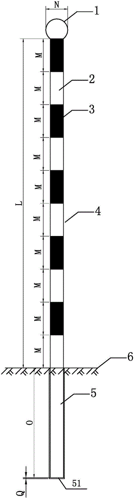
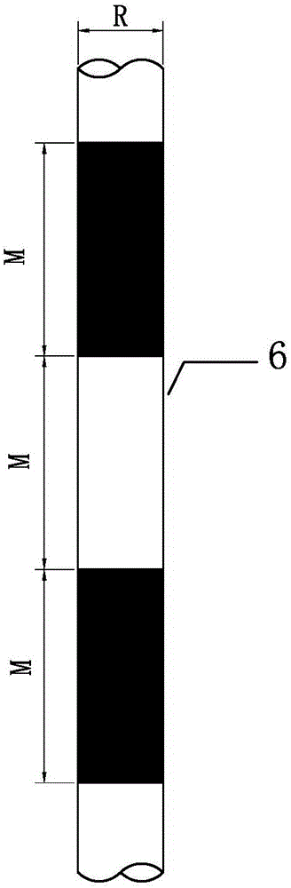
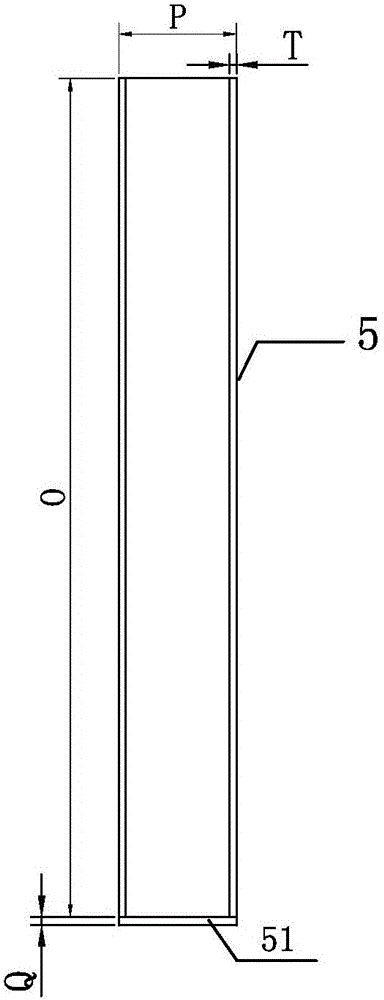
[0028] Such as Figure 1 to Figure 3 As shown, the vehicle driving boundary induction rod for low visibility roads of the present invention includes a hollow cylindrical rod body 4 and a steel sleeve 5 . The steel casing 5 is pre-embedded in the slope on the subgrade 6, specifically, as Figure 4 , Figure 5 As shown, in order to avoid affecting the winter snow removal operation face of the highway, the horizontal distance D between the embedded point of the steel casing 5 in the slope and the shoulder of the roadbed 6 is 0.1m. The bottom of the rod body 4 is inserted downward into the steel casing 5, and the rod body 4 is alternately provided with light-emitting parts 1 2 and 2 3 with the same length along its axial direction from top to bottom. The light-emitting part one 2 and the light-emitting part two 3 can be all reflective films with different color shades attached on the rod body 4, for example, the light-emitting part one 2 can adopt red or yellow dark reflective f...


PUM

PropertyMeasurementUnit
Lengthaaaaaaaaaa
Rod diameteraaaaaaaaaa
Lengthaaaaaaaaaa

Abstract

The invention provides a vehicle travelling boundary inducing rod for a low-visibility road. The boundary inducing rod comprises a hollow cylindrical rod body and a steel casing, wherein the steel casing is buried in the side slope on the subgrade; the bottom of the rod body is inserted into the steel casing; a luminescent part I and a luminescent part II with the same length M are alternately arranged on the rod body in a sectionalized manner along the axial direction of the rod body; and a luminscent part III is arranged at the top of the rod body. The invention aims at providing the vehicle travelling boundary inducing rod for a low-visibility road, which has the advantages of simple structure, low cost, simple construction and good induction performance.

Description


Claims


Application Information

Patent Timeline
Owner 新疆交通科学研究院有限责任公司
Why Eureka
Try Eureka