Road traffic guardrail capable of buffering and absorbing impact

A road traffic and guardrail technology, which is applied in the field of traffic guardrails, can solve the problems of large friction between the elastic rotating body and the rotating receiving plate, poor absorption and buffering impact, and inability to absorb impacts well, so as to achieve convenient and fast installation and prevent The effect of water ingress and simple structure

Active Publication Date: 2016-10-12
ANHUI MINGXIN METAL PROD CO LTD
7 Cites 26 Cited by

AI-Extracted Technical Summary

Problems solved by technology

[0006] The structures of the above three guardrails are relatively complex. In actual use, due to structural limitations, the installation is time-consuming, labor-intensive, and work-efficient. In addition, due to the large friction betwe...

Method used

In order to enhance the applicability of the guardrail of the present invention, the installation landing portion of the long column 100a is connected with a base 20, and mounting holes are all established on the base, so that the anti-collision guardrail of the present invention can be installed on the concrete ground, and can also Put the anchor screws through the installation holes and pre-embed them in the concrete.
In order to manufacture needs, in Fig. 1 and Fig. 14, described elastic rotating body 11 can be one-piece type or split type, be provided with annular groove along the circumferential direction surface of described elastic rotating body 11, in the groove Adhesive reflective tape 110; or a reflective layer integrated with the elastic rotating bod...

Abstract

The invention discloses a road traffic guardrail capable of buffering and absorbing impact. The road traffic guardrail is characterized by comprising fastening pieces; each fastening piece is provided with two ends and a connecting part used for connecting the two ends, wherein the two ends are used for applying force to an upper horizontal column or a lower horizontal column; power is transmitted to the connecting part from the two ends; and the upper horizontal column or the lower horizontal column is subjected to the force and moves relative to a corresponding round tube stand column, so that the upper horizontal column or the lower horizontal column is fixed to the round tube stand column. The road traffic guardrail capable of buffering and absorbing impact is simple in structure; the fastening pieces are adopted for fixing the upper horizontal column and the lower horizontal column; on the one hand, the fastening pieces are high in strength and guarantee the anti-impact performance of the upper horizontal column and the lower horizontal column, on the other hand, the upper horizontal column and the lower horizontal column can move relative to the round tube stand columns only by applying force to the connecting parts of the fastening pieces in the mounting process, and therefore, fixation is achieved; mounting is convenient and fast, and the labor efficiency is greatly improved; and at the same time, a smaller number of screw rods are used, and the production cost is lowered.

Application Domain

Technology Topic

Image

  • Road traffic guardrail capable of buffering and absorbing impact
  • Road traffic guardrail capable of buffering and absorbing impact
  • Road traffic guardrail capable of buffering and absorbing impact

Examples

  • Experimental program(1)

Example Embodiment

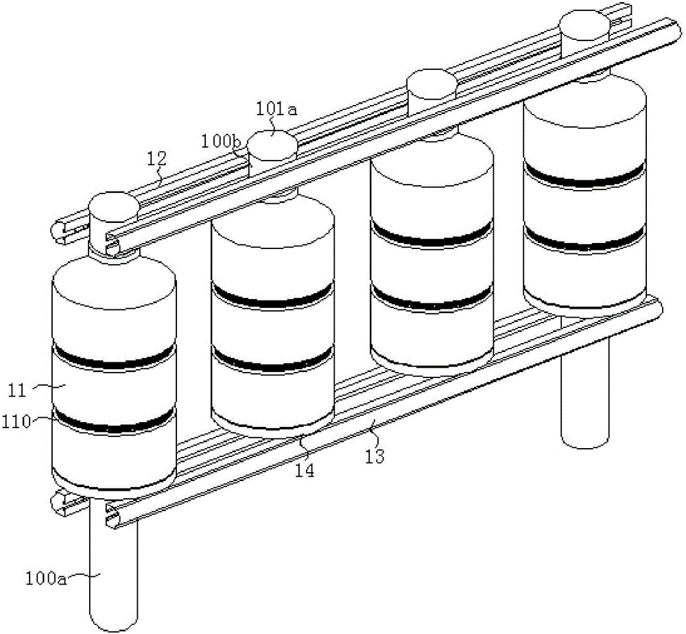
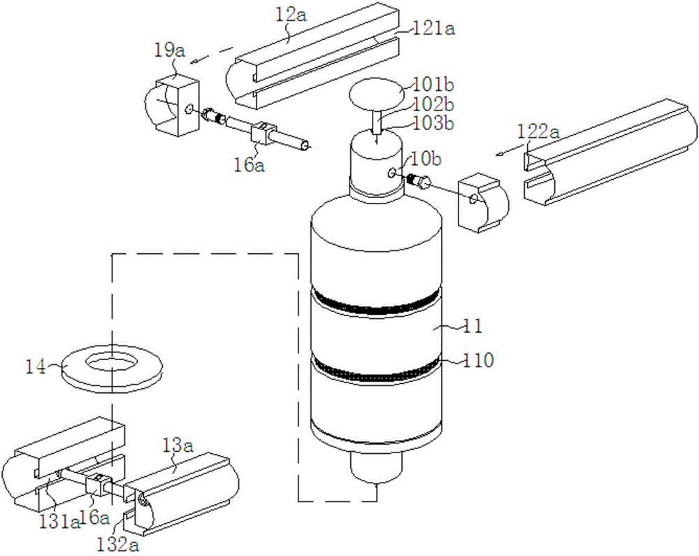
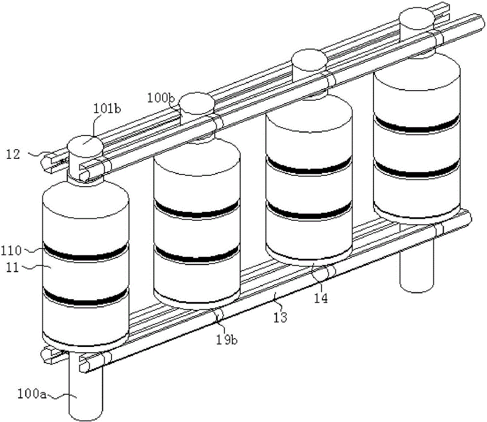
[0047] First of all, it should be noted that the specific structure, characteristics, and advantages of the road traffic barrier that can buffer and absorb impacts of the present invention will be explained in detail below by way of examples. However, all the descriptions are only for illustration, and should not be used. It is understood to form any limitation on the present invention. In addition, any single technical feature described or implied in each embodiment mentioned herein, or any single technical feature displayed or implied in each drawing, can still be used in these technical features (or their equivalents). ) Continue to perform any combination or deletion, so as to obtain more other embodiments of the present invention that may not be directly mentioned in this article. In addition, for the sake of simplification of the drawings, the same or similar parts and features may only be labeled in one or several places in the same drawing.
[0048] Please refer to Figure 1 to Figure 15 The following examples are given to illustrate the road traffic guardrail capable of buffering and absorbing the impact of the present invention.
[0049] As shown in the figure, a road traffic guardrail capable of buffering and absorbing impacts of the present invention includes a round tube column 10, an elastic rotating body 11 sleeved on the round tube column, an upper rail 12 arranged above the elastic rotating body, and The lower horizontal rail 13 underneath it, the rotating receiving member 14 sleeved on the column of the round tube and arranged between the lower horizontal rail and the elastic rotating body, further includes a fastener 16 having two ends And the connecting part used to connect the two ends, the two ends apply force to the upper rail or the lower rail respectively, and the connecting part transmits force to the two ends, so that the upper rail 12 or the lower rail 13 is stressed Moving relative to the round tube column 10 realizes the fixing of the upper horizontal rail 12 or the lower horizontal rail 13 on the circular tube column 10.
[0050] in Figure 7 , Figure 8 Wherein, the fastener 16a may have a base 161a, a first threaded sleeve 162a movable relative to the base, a second threaded sleeve 163a fixed relative to the base, and a first threaded sleeve, The two screws 164a matched with the second threaded sleeve, the base is hollow and at least one end is open, the base is built with a bevel gear 165a, and the bevel gear is provided with a rotating hole 166a along the center corresponding to the through hole provided on the base. The gear is fixed in the base through a positioning ring (not marked in the figure); a rack is arranged inside the movable sleeve and extends into the base, and the bevel gear is matched with the rack.
[0051] Alternatively, the fastener 16b may also have a base 161b, a first threaded sleeve 162b that moves relative to the base, a second threaded sleeve 163b that moves relative to the base, and a first threaded sleeve respectively. The two screw rods 164b matched by the tube and the second threaded sleeve. The base is hollow and at least one end is open. The base is built with a bevel gear 165b. The bevel gear is provided with a rotating hole 166b along the center corresponding to the through hole provided on the base. , The bevel gear is fixed in the base through the positioning ring (not marked in the figure); the inner side of the movable sleeve is provided with a rack and extends into the base, and the bevel gear is matched with the rack.
[0052] The fasteners 16a and 16b of the above two structures are split type, and the screw rods can be tightened into the two sides of the cylindrical column 10 during use, which is convenient for installation.
[0053] Such as Picture 9 As shown, the fastener 16c can also be an integral screw structure, and its two ends are provided with mutually opposite threads 161c. The middle of the fastener has at least two opposite stress surfaces 162c, and the fastener directly penetrates In the round pipe column 10, both ends are limited by nuts 163c. The wrench extends into the round pipe column and clamps the middle of the fastener. After force is applied, the nut at both ends can be tightened.
[0054] In order to reduce the friction on the bottom of the elastic rotating body 11, the elastic rotating body 11 can be rotated freely. The rotating receiving member 14 has a fixed part and a rotating part that rotates relative to the fixed part. The fixed part is positioned on the lower transverse On the fence 13, the rotating part carries the elastic rotating body 11, which is placed above the fixed part and rotates freely around the cylindrical column 10.
[0055] Such as Picture 10 , Picture 11 As shown, the rotating receiving member 14 may adopt the following structure: 1) The rotating receiving member 14a includes a bottom bracket 141a and a flange 142a with a cover plate 143a. The bottom bracket and the flange are sleeved on the round pipe from bottom to top in sequence. On the column 10, a ring groove is opened along the center of the bottom bracket, balls are provided along the center of the flange corresponding to the ring groove, and the elastic rotating body 11 is received on the cover plate 143a of the flange: 2) The rotating receiving member 14b includes a bottom bracket 141b and a supporting plate 142b with rollers. The bottom bracket and the supporting plate are sequentially sleeved on the cylindrical column 10 from bottom to top, and the elastic rotating body 11 is placed on the supporting plate 142b.
[0056] From Image 6 It can be seen that the guardrail also includes a U-shaped connecting bracket 15. The U-shaped connecting bracket 15 is provided with through holes on three sides, and the upper horizontal rail 12 and the lower horizontal rail 13 are provided with through holes and the U-shaped connecting bracket 15 The two longitudinal through holes correspond to each other, and the two longitudinal through holes of the U-shaped connecting bracket and the through holes on the upper horizontal rail 12 or the lower horizontal rail 13 are inserted through the first screw rod 17 and fixed; the round pipe column 10 is provided with a through hole and a U-shaped The horizontal through holes of the connecting bracket correspond to each other, and the through holes of the circular pipe column 10 and the horizontal through holes of the U-shaped connecting bracket 15 are fixed through the fastener 16.
[0057] On the basis of the above structure, combined Image 6 , Picture 10 , Picture 11 The bottom brackets 141a and 141b are circular rings. The outer diameter of the circular ring is larger than the diameter of the cylindrical column 10 and smaller than the bottom diameter of the elastic rotating body 11. The circular ring is symmetrically provided with notches 1411a, 1411b, the notches and the first screw The heads of 17 are matched, the ring is placed stably, and is limited by the head of the first screw, and will not rotate with the elastic rotating body 11, ensuring the normal rotation of the elastic rotating body.
[0058] in Image 6 In order to effectively avoid hard contact between the upper rail 12 or the lower rail 13 and the nut 163c or the screw heads of the screws 164a and 164b of the fastener 16, on the other hand, in order to achieve a good impact Bar cushioning effect, a cushion 18 is provided between the U-shaped connecting bracket 15 and the upper horizontal rail 12 or the lower horizontal rail 13. After the fasteners are installed, the nut or the screw head of the screw is located on the U-shaped connecting bracket In 15, the cushion is against the screw head of the nut or screw.
[0059] Further, the cushion 18 is made of rubber material or water glass material or silicone material, its size matches the size of the U-shaped connecting bracket 15, and the thickness is the same as that of the nut 163c or the screw 164a, 164b Match the width of the screw head.
[0060] From Figure 1 to Figure 4 It can be seen that the guardrail also includes a casing 19, the cross-sectional shape of the casing 19 is consistent with the cross-sectional shape of the upper rail 12 or the lower rail 13, and the cross-sectional size of the casing is slightly smaller or slightly larger than the upper rail 12 or the cross-section size of the lower rail 13, the casing is fixed on the round pipe column 10 by a fastener 16, and the upper rail 12 or the lower rail 13 is sleeved outside or inside the casing 19, respectively.
[0061] So like figure 2 As shown, the shape and structure of the upper horizontal bar 12a and the lower horizontal bar 13a are the same. The two horizontal bars are bread tubes, square tubes, D-shaped tubes or round tubes, and first notches 121a and 131a are provided on the tube wall. With the through hole, the first notch is retracted to form a first force platform 122a, the width of the first notch matches the height of the nut 163c, and the width of the first force platform matches the width of the nut 163c; the corresponding sleeve The tube 19a is a bread tube, a square tube, a D-shaped tube or a round tube, and the upper rail or the lower rail can be sleeved on the outside of the casing.
[0062] Such as Figure 4 As shown, it can also be that the shape and structure of the upper horizontal bar 12b and the lower horizontal bar 13b are the same. The two horizontal bars are bread tubes or square tubes or D-shaped tubes or round tubes, and a second notch 121b is provided on the tube wall. , 131b and its width is greater than the height of the nut 163c; the corresponding sleeve 19b is a bread tube or a square tube or a D-shaped tube or a round tube. The tube wall is provided with a third notch 191b. The third notch is retracted to form a third receiving Force platform 192b, the width of the third notch matches the height of the nut 163c, the width of the third force platform matches the width of the nut 163c, the upper rail or the lower rail can be sleeved inside the sleeve 19b .
[0063] In addition, combine Picture 12 , The said round pipe column 10a is provided with an end cover 101a, the lower end of the end cover is provided with threads, and the corresponding round pipe column is provided with threads. After the fastener 16 is fixed, the end cover is screwed on and the end cover is firmly fixed There is no need for welding, which is beneficial to prevent water from entering the column of the round tube and improve the corrosion resistance.
[0064] in figure 2 , Figure 4 , Image 6 and Figure 13 In the above-mentioned structure of the fasteners 16a, 16b, the bevel gears 165a, 165b will rotate when the two ends are stressed. In order to lock the bevel gears of the fasteners, the cylindrical column 10b is provided with There is an end cap 101b. The lower center of the end cap is provided with a connecting rod 102b. The lower two sides of the connecting rod are provided with barbs 103b. The size of the connecting rod is consistent with the size of the rotating holes 166a and 166b. The connecting rod is directly inserted into the rotating In the hole, it is limited by the barb.
[0065] For manufacturing needs, in figure 1 with Figure 14 Wherein, the elastic rotating body 11 may be an integral type or a split type, an annular groove is provided on the surface of the elastic rotating body 11 along the circumferential direction, and the reflective tape 110 is bonded in the groove; or the surface of the elastic rotating body is compounded There is a reflective layer integrated with the elastic rotating body, which is beneficial to remind the car driver to pay attention to the road conditions and ensure safe driving.
[0066] Such as figure 1 with Figure 15 As shown, under the requirements of strength, the round tube column 10 can be alternately arranged with long columns 100a and short columns 100b. The long columns are connected to the upper rail 12 and the lower rail 13 and extend downward to the lower rail. An installation landing part is formed below the rail, and the two ends of the short column are respectively connected with the upper rail 12 and the lower rail 13.
[0067] In order to enhance the applicability of the guardrail of the present invention, the installation floor part of the long column 100a is connected with a base 20, and mounting holes are provided on the base, so that the anti-collision guardrail of the present invention can be installed on the concrete ground and the foot The screws are inserted through the mounting holes and embedded in the concrete.
[0068] The above is only an example to explain in detail the road traffic guardrail of the present invention that can buffer and absorb impacts. These examples are only used to illustrate the principle and implementation of the present invention, not to limit the present invention, and do not depart from the present invention. Given the spirit and scope, those skilled in the art can also make various modifications and improvements. Therefore, all equivalent technical solutions shall belong to the scope of the present invention and be defined by the various claims of the present invention.

PUM

no PUM

Description & Claims & Application Information

We can also present the details of the Description, Claims and Application information to help users get a comprehensive understanding of the technical details of the patent, such as background art, summary of invention, brief description of drawings, description of embodiments, and other original content. On the other hand, users can also determine the specific scope of protection of the technology through the list of claims; as well as understand the changes in the life cycle of the technology with the presentation of the patent timeline. Login to view more.

Similar technology patents

Classification and recommendation of technical efficacy words

  • Simple structure
  • High strength

Beam expanding optical element, beam expansion method, image display apparatus, and head-mounted display

InactiveUS20070188837A1Reduce color unevennessSimple structureOptical light guidesSubstrate with hologramHead worn displayLight wave
Owner:KONICA MINOLTA INC

Microlithographic projection exposure apparatus

InactiveUS20050068499A1Simple structureReliable and low-maintenance operationProjectorsPhotomechanical exposure apparatusCamera lensPhysics
Owner:CARL ZEISS SMT GMBH
Why Eureka
Try Eureka