
Connection limiter used for transition section of concrete column and concrete-filled steel tubular column

A technology for concrete-filled steel tubular columns and concrete columns, which is applied in construction, building structure and other directions, can solve problems such as difficult operation and difficult quality control, and achieve the effect of reducing the amount of measures and saving costs.

Active Publication Date: 2016-10-12
CHINA CONSTR STEEL STRUCTURE CORP LTD
View PDF6 Cites 2 Cited by
  • Summary
  • Abstract
  • Description
  • Claims
  • Application Information

AI Technical Summary

Problems solved by technology

Because the outer wall of the steel pipe column is higher or equal to the height of the ribs, when welding the cross-shaped plate and the ribs of the steel column in this way, the operation is relatively difficult and the quality is difficult to control

Method used


Image

  • Connection limiter used for transition section of concrete column and concrete-filled steel tubular column
  • Connection limiter used for transition section of concrete column and concrete-filled steel tubular column
  • Connection limiter used for transition section of concrete column and concrete-filled steel tubular column

Examples


specific Embodiment approach

[0017] The preferred specific embodiment of the connection limiter for the transition section between a concrete column and a concrete-filled steel tube column of the present invention is:

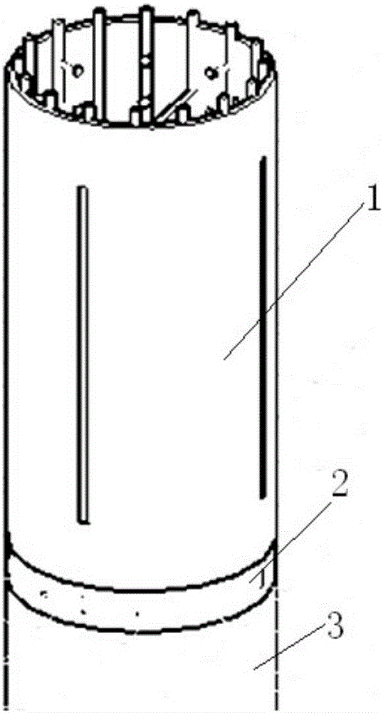
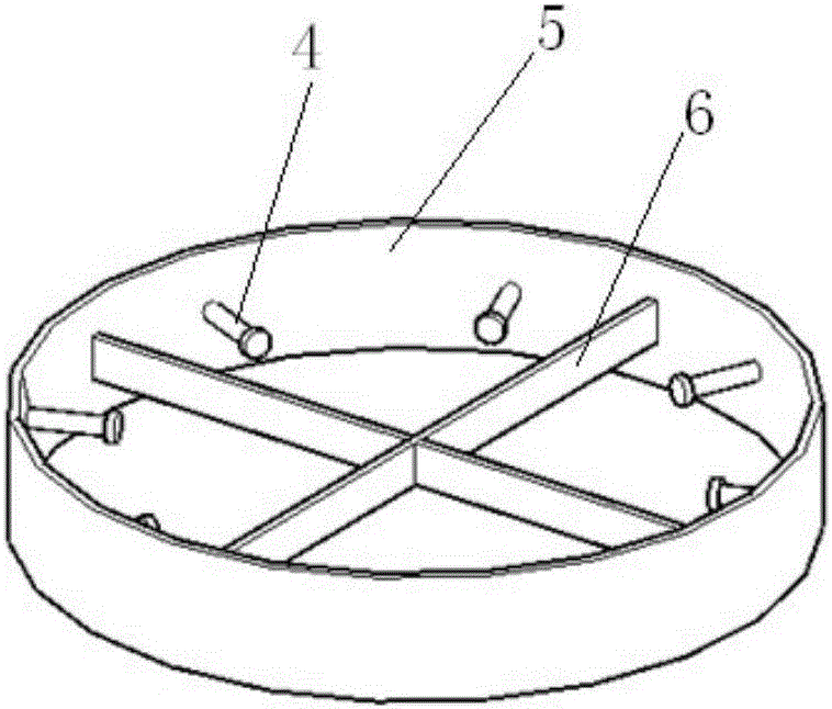
[0018] The connection limiter is arranged between the lower concrete column and the upper steel tubular concrete column, and includes a ring plate, and a rib plate and a stud are arranged in the ring plate. The thickness and direction are consistent with the position, size, thickness and direction of the ribs and studs inside the CFST column, and are used to limit the reinforcement of the concrete column.

[0019] The outer diameter of the steel bar stopper is consistent with the outer diameter of the concrete column and the steel tube concrete column.

[0020] The height of the ring plate is 50mm to 150mm, and the thickness is 8mm to 12mm.

[0021] The connection limiter used for the transition section between a concrete column and a concrete-filled steel tube column of the invention sol...

specific Embodiment

[0026] The basic composition of the connection limiter for the transition between concrete columns and concrete-filled steel tubular columns:

[0027] like Figure 5a , Figure 5b , Figure 5c As shown in the figure, the connection limiter used for the transition between the concrete column and the concrete-filled steel tube column is mainly composed of three parts: the ring plate, the rib plate and the stud.

[0028] 1) Design of ribs and studs:

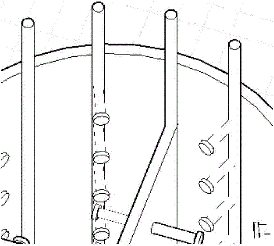
[0029] The position, size, thickness and direction of the rib and studs should be consistent with the upper steel pipe column, so as to limit the position of the steel bar, and the height and thickness of the rib should be appropriate. .

[0030] 2) Ring plate design:

[0031] In order to avoid the situation that the concrete column formwork cannot be closed after the reinforcement stopper is installed, the outer diameter of the reinforcement stopper should be consistent with the outer diameter of the concrete column and the st...


PUM


Abstract

The invention discloses a connection limiter used for a transition section of a concrete column and a concrete-filled steel tubular column. The connection limiter is arranged between the concrete column on the lower portion and the concrete-filled steel tubular column on the upper portion, and comprises an annular plate; rib plates and pins are arranged inside the annular plate; and the position, size, thickness and direction of the rib plates and the pins in the annular plate are consistent with those of rib plates and pins inside the concrete-filled steel tubular column, and the rib plates and the pins are used for limiting steel bars of the concrete column. The problem of collision between column rebars of the concrete column and rib plates of the concrete-filled steel tubular column is solved, convenience is provided for positioning and installation of the steel tubular column, the number of measures is reduced, and the cost is reduced.

Description

technical field [0001] The invention relates to a steel structure construction member, in particular to a connection limiter used for the transition section between a concrete column and a concrete-filled steel tube column. Background technique [0002] In the construction of steel structure, at the position where the concrete column and the steel pipe column are connected, if the column reinforcement of the concrete column needs to pass through the steel pipe column, it is easy to cause the column reinforcement to collide with the inner rib of the steel pipe column column. At this time, the concrete column has generally been poured. , the column bars are difficult to move, and the steel pipe columns are difficult to install or even impossible to install. [0003] At present, in the transition section between the concrete column and the CFST column, the method generally adopted is to embed a section of H-beam with a length of 1500mm in the concrete column. The cross-shaped ...

Claims


Application Information

Patent Timeline
Patent Type & Authority Applications(China)
IPC IPC(8): E04B1/21
CPCE04B1/215
Inventor 黄晓康吴洪涛张希博陈晓冬侯家骐彭湃吕涛周坤
Owner CHINA CONSTR STEEL STRUCTURE CORP LTD
Learn More