Replaceable composite steel plate energy dissipation steel structure beam-column joint

A beam-column joint and steel structure technology, applied in building components, building structures, earthquake-proof and other directions, can solve the problems of insufficient energy dissipation capacity, difficult to deform and destroy centralized replaceable components, etc. Simple, well-defined effects

Inactive Publication Date: 2016-10-12
HARBIN INST OF TECH
View PDF4 Cites 28 Cited by
  • Summary
  • Abstract
  • Description
  • Claims
  • Application Information

AI Technical Summary

Problems solved by technology

[0004] At present, many scholars have set various forms of replaceable components at the beam-column joints of the frame structure system, but the research mainly focuses on setting the beam-column joints as replaceable components or setting up replaceable

Method used


Image

  • Replaceable composite steel plate energy dissipation steel structure beam-column joint
  • Replaceable composite steel plate energy dissipation steel structure beam-column joint
  • Replaceable composite steel plate energy dissipation steel structure beam-column joint

Examples


Example Embodiment

[0034] Example 1

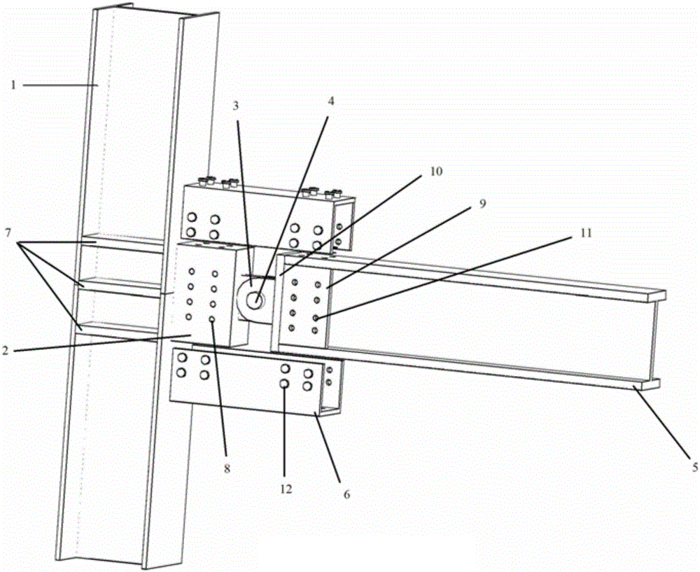
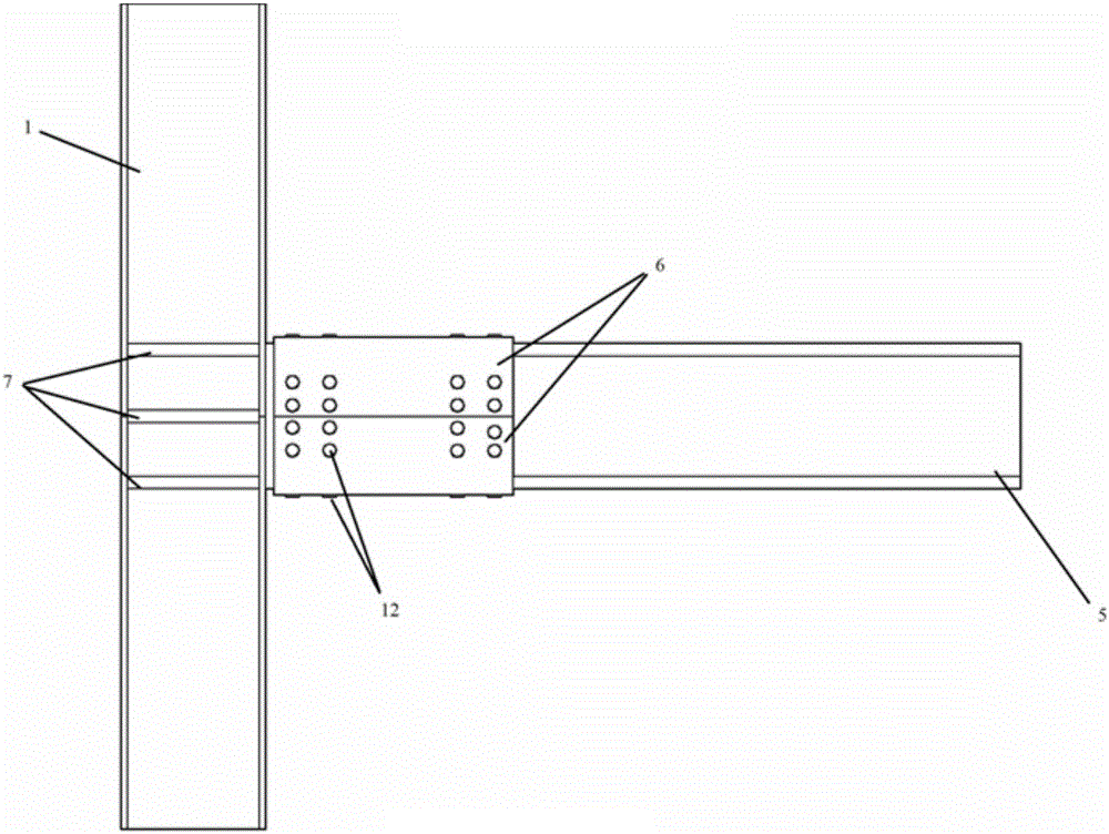
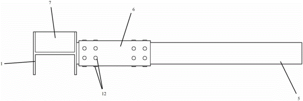
[0035] like Figure 1-13 As shown, a beam-column joint of energy-dissipating steel structure with replaceable combined steel plates includes a steel column 1, a short beam section 2 at the end of the column, an ear plate 3, a pin shaft 4, a main beam 5 and upper and lower combined steel plates 6, and a steel column 1 and one end of the short beam section 2 at the column end are connected by welding, the main beam 5 and the short beam section 2 at the column end form a hinged connection through the ear plate 3 and the pin shaft 4, and the upper and lower combined steel plates 6 are connected to the short column end section through high-strength bolts 12 The beam section 2 and the main beam 5 are fastened and connected to form a whole.

[0036] The steel column 1 independently selects the cross-section type according to the structural design requirements. In this example, H-shaped steel is selected. On the steel column 1, a plurality of horizontal stiffening ...

Example Embodiment

[0041] Example 2

[0042] The structure of this embodiment is basically the same as that of Embodiment 1, except that the short beam section 2 at the end of the column is H-shaped steel, and is provided with a vertical side panel 9 parallel to the main beam and an end plate 10 perpendicular to the main beam. Bolt holes 11 are drilled on four faces parallel to the main beam near one end of the lug plate. The cross-sectional shape of the upper and lower combined steel plates 6 is L-shaped in this example.


PUM


Abstract

The invention discloses a replaceable composite steel plate energy dissipation steel structure beam-column joint. The steel structure beam-column joint comprises a steel column (1), an end-column short beam section (2), an ear plate (3), a hinge pin (4), a main beam (5) and upper and lower composite steel plates (6); the steel column (1) is connected with one end of the end-column short beam section (2), the main beam (5) is hinged to the end-column short beam section (2) through the ear plate (3) and the hinge pin (4), and the upper and lower composite steel plates (6) and the end-column short beam section (2) and the main beam (5) are tightly connected into a whole. According to the beam-column joint, stress is reasonable and definite, the situation that structural deformation and energy dissipation are concentrated on the composite steel plates can be achieved under the rare earthquake action, only the composite steel plates enter plastic energy dissipation, the rest part and the structure body are within the elastic range, and rapid restoration of the whole function of the structure can be achieved by replacing the composite steel plates (6) after the earthquake action.

Description

technical field [0001] The invention belongs to the technical field of building structures and relates to a beam-column node of an energy-dissipating steel structure with replaceable combined steel plates. Background technique [0002] Steel structure has a series of advantages such as high strength, light weight, good seismic performance, fast construction speed, low foundation cost, small occupied area, high degree of industrialization, beautiful appearance, etc. Compared with concrete structure, it has the advantages of environmental protection and reusability , is also a structural type that is easy to industrialize. The connection node between the beam and the column is a key component to ensure that the beam and the column work together to form a structural whole. Although the beam-column joints have been greatly optimized and improved in recent years, showing superior seismic performance, but because the seismic design idea is based on the formation of plastic hinges...

Claims


Application Information

Patent Timeline
IPC IPC(8): E04B1/58E04B1/24E04B1/98E04H9/02
CPCE04B1/2403E04B1/5812E04B1/98E04B2001/2415E04B2001/2448E04H9/024
Inventor 欧进萍王晨刘敏
Owner HARBIN INST OF TECH
Why Eureka
Try Eureka