
A cable support structure and installation method of a shaft-hinged cable crane

A cable crane and cable support technology, which is applied to cable cranes, cranes, traveling mechanisms, etc., can solve the problems affecting the safety of cable crane equipment, the easy overturning of the cable support, and the easy overturning of the trolley, so as to achieve light weight and stress Clear and reasonable, avoid the effect of mutual friction

Active Publication Date: 2017-11-14
HUNAN ZHONGNAN BRIDGE INSTALLATION ENG +1
View PDF8 Cites 0 Cited by
  • Summary
  • Abstract
  • Description
  • Claims
  • Application Information

AI Technical Summary

Problems solved by technology

[0004] At present, most of the trolleys of the self-propelled cable support use single-row walking wheels. The cable harness is wide, and the cable harness is easy to overturn when walking on the load-bearing cable, and because the cable bracket is just connected to the trolley, the supporting wheels supporting the hoisting cable and the traction cable are vertically facing each other due to the unbalanced horizontal force on both sides. The unbalanced torque generated by the trolley also causes the trolley to overturn easily, thus failing to achieve the effect of the support cable and affecting the safety of the cable crane equipment

Method used


Image

  • A cable support structure and installation method of a shaft-hinged cable crane
  • A cable support structure and installation method of a shaft-hinged cable crane
  • A cable support structure and installation method of a shaft-hinged cable crane

Examples


Embodiment Construction

[0033] The present invention will be described in detail below with reference to the accompanying drawings and examples. It should be noted that, in the case of no conflict, the embodiments of the present invention and the features in the embodiments can be combined with each other. For the convenience of description, if the words "front", "rear", "left" and "right" appear in the following, it only means that they are consistent with the front, rear, left and right directions of the drawings themselves, and do not limit the structure.

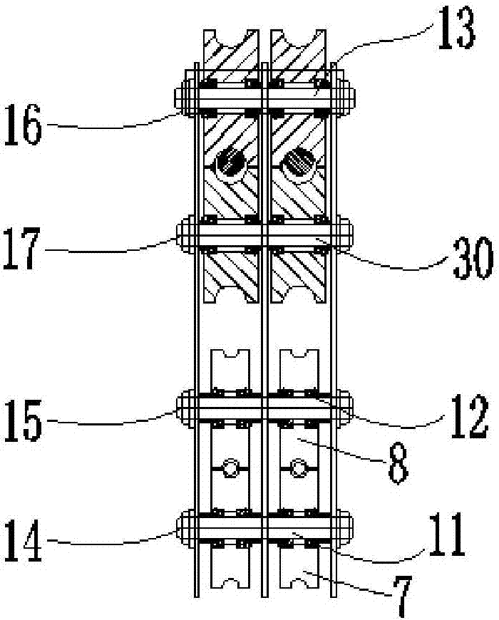
[0034] A shaft-hinged cable crane support structure, such as Figure 1-4 As shown, the first support device 1, the second support device 2, the support bracket 3, the trolley 4, the hanger shaft 5, the trolley wheel 6, the hoisting wheel 7, the hoisting wheel 8, the bearing Soto wheel 9, load-bearing soto shaft 10, first pin 11, second pin 12, third pin 13, first anti-off nut 14, second anti-off nut 15, third anti-off nut 16, The fourth anti-...


PUM


Abstract

The invention discloses a cable catcher structure of a shaft-hinged cable crane and its mounting method. The cable catcher structure of the shaft-hinged cable crane includes a plurality of first catchers and at least one second catchers, both of which comprise a support bracket and a trolley, and the first catchers and the second catchers are connected by ropes. The top end of the trolley is provided with a plurality of small wheels which are placed over load cables when used, and the bottom end of the support bracket is provided with a plurality of hoisting wheels, the hoisting wheels are provided above the hoisting cable pressing wheels, the trolley of the first catchers is integral with the support bracket of the first catchers, and the lower part of the trolley of the second catchers is connected with the upper part of the support bracket of the second catchers through a hanger shaft; the loader wheels are arranged under the small wheels of the first catchers, and loader cable support shafts are arranged below the small wheels of the second catchers. The cable catcher structure ensures that the torque on the trolley from the cable support is zero under the action of the weight of the hoisting cables and the cable force.

Description

technical field [0001] The invention relates to an auxiliary device used in a cable crane in a bridge construction project and an installation method thereof, in particular to a shaft-hinged cable crane structure and an installation method thereof. Background technique [0002] Cable cranes are lifting equipment with cables as the load-bearing structure. In bridge engineering construction, they are usually used in bridge engineering construction with narrow sites, steep mountains and valleys on both sides, navigable rivers, and roads or railways that are open to traffic. [0003] When the cable crane uses the reciprocating cycle of the traction cable, during the use of large cable cranes, the cable crane cannot operate normally due to the failure of the support device or the hook of the cable crane cannot be lowered normally under no-load conditions. , which brings a greater safety hazard to the safe operation of the cable crane equipment. At present, self-propelled cable s...

Claims


Application Information

Patent Timeline
Patent Type & Authority Patents(China)
IPC IPC(8): B66C21/10B66C9/08
CPCB66C9/08B66C21/10B66C2700/011
Inventor 刘均平杨世湘张艳春陈维超彭凤禄杨鑫彭华东张军彭际济
Owner HUNAN ZHONGNAN BRIDGE INSTALLATION ENG
Learn More