
Suspended and floor fan capable of automatically controlling airflow

A dual-purpose, fan technology, applied in pump control, non-variable pumps, machines/engines, etc., can solve the problems of unable to adjust the wind speed, troublesome fan speed, poor maintenance, etc., to reduce the occupied space and ensure the service life Effect

Active Publication Date: 2016-10-12
全椒县杨国电器有限公司
View PDF9 Cites 1 Cited by
  • Summary
  • Abstract
  • Description
  • Claims
  • Application Information

AI Technical Summary

Problems solved by technology

[0004] The invention provides a dual-purpose fan for suspension and floor type with automatic wind control. By providing a suspension box, a hanging ring, an electric telescopic rod, a resistance wire, a frequency converter and a timing knob, it solves the problem of the floor-type and floor-type fans in existing households. Difficulty in suspension switching, poor maintenance and troublesome adjustment of fan speed or inappropriate and reasonable wind speed adjustment

Method used


Image

  • Suspended and floor fan capable of automatically controlling airflow
  • Suspended and floor fan capable of automatically controlling airflow

Examples


Embodiment

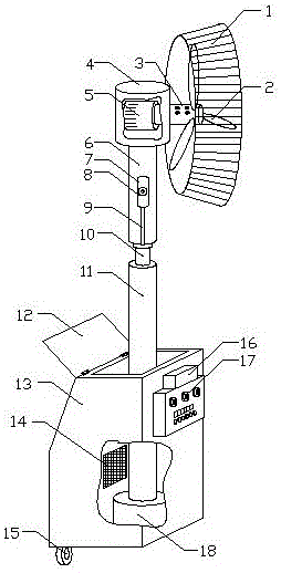
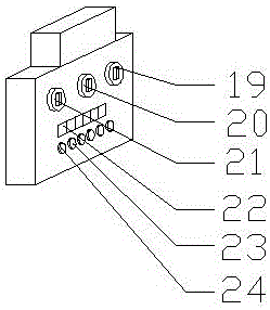
[0021] Example: such as Figure 1-2 As shown, the present invention provides a suspension and ground dual-purpose fan with automatic wind control, including a first rotating rod 10 and an outer protection rod 6, the outer wall of the first rotating rod 10 is socketed with the outer protection rod 6, and the bottom end is connected to The telescopic rod 11, the inside of the outer protective rod 6 is provided with an oil chamber 7, the bottom of the oil chamber 7 is connected to the lower oil pipe 9, and the lower oil pipe 9 communicates with the oil tank 25, and the top of the outer protective rod 6 is equipped with a protective cover 4, a protective cover 4 A motor 5 is installed inside, one end of the motor 5 is connected to the second rotating rod 3, one end of the second rotating rod 3 is connected to three blades 2, a circular protective frame 1 is installed on the outside of one end, and the lower part of the electric telescopic rod 11 is provided with a suspension Box 1...


PUM


Abstract

The invention discloses a suspended and floor fan capable of automatically controlling airflow. The suspended and floor fan comprises a first rotating rod and an outer protective rod. The outer wall of the first rotating rod is sleeved with the outer protective rod. The bottom end of the first rotating rod is connected with an electric telescopic rod. An oil cavity is arranged inside the outer protective rod. The bottom end of the oil cavity is connected with an oil drainage pipe. The oil drainage pipe is made communicated with an oil groove. The top end of the outer protective rod is provided with a protective cover. A motor is installed inside the protective cover. One end of motor is connected with a second rotating rod. One end of the second rotating rod is connected with three blades, and the outer side of the other end of the second rotating rod is provided with a circular protective frame. The lower portion of the electric telescopic rod is provided with a suspended box, and the bottom end of the electric telescopic rod is provided with a fastener. The outer wall of the suspended box is provided with a control panel. The inner wall of the suspended box is provided with a resistance wire. By arranging the suspended box and a hanging ring, the fan can be suspended to a wall; due to the bent design of the upper end of the suspended box, the circular protective frame will not touch the wall when rotating, so that safe suspension of the fan is achieved, and rapid switching of floor and suspension is achieved. In the air speed adjusting process, the system is controlled trough a temperature and humidity sensor to intelligently adjust the appropriate air speed.

Description

technical field [0001] The invention relates to a household fan, in particular to a dual-purpose fan for suspension and ground with automatic wind control, belonging to the technical field of household appliances. Background technique [0002] Electric fans, Japan and South Korea are called fans. Modern fans use electricity as energy, so they are also called electric fans. They are called electric winds in Taiwanese. They are household appliances that use electricity to drive the fan blades to rotate to accelerate the air circulation , mainly used for cooling and relieving heat and air circulation. Widely used in homes, offices, shops, hospitals and hotels and other places. The electric fan is mainly composed of fan head, fan blade, net cover and control device and other components. The fan head includes a motor, front and rear end covers, and an oscillating air supply mechanism. The main component of an electric fan is an AC motor. Its working principle is that the ener...

Claims


Application Information

Patent Timeline
Patent Type & Authority Applications(China)
IPC IPC(8): F04D29/64F04D25/08F04D27/00F04D29/063
CPCF04D25/08F04D25/088F04D27/004F04D29/063F04D29/646
Inventor 郑仕群
Owner 全椒县杨国电器有限公司
Learn More