Automatic light source adjusting device for machine vision system
A technology of a light source device and a linear motor, applied in the field of lighting, can solve problems such as being unfavorable to the automation and flexibility of a vision system, cumbersome and unsatisfactory adjustment of illumination uniformity, and achieve the best lighting effect. Effect
- Summary
- Abstract
- Description
- Claims
- Application Information
AI Technical Summary
Problems solved by technology
Method used
Image
Examples
Embodiment 1
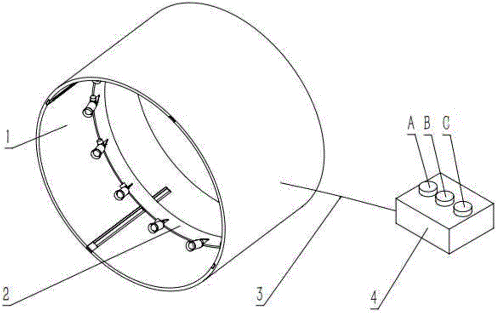
[0028] Refer to attached figure 1 In this embodiment, the device for automatically adjusting the dimming light source includes: a sleeve fixing assembly 1 , a support ring sliding assembly 2 , a connecting control line 3 , and a control module 4 . The control module 4 includes: a button A for automatically adjusting the light source distance.
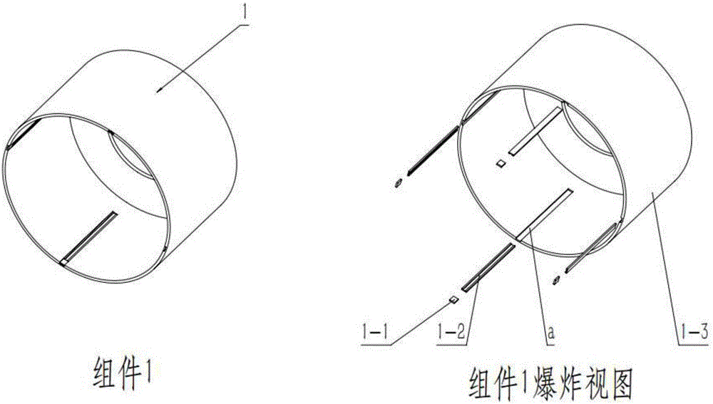
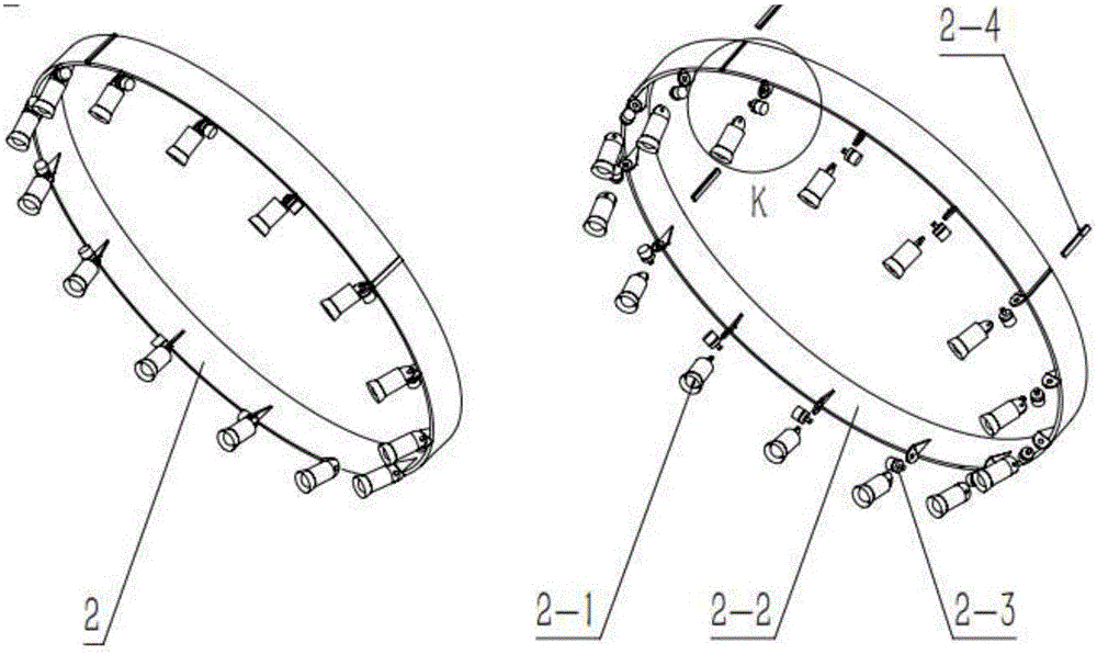
[0029] Refer to attached figure 2 , wherein the sleeve fixing assembly 1 includes: a linear motor stator part 1-2, and a sleeve 1-3. A sleeve inner wall groove a is provided on the inner wall of the sleeve. The linear motor stator part 1-2 is fixed in the sleeve inner wall groove a inside the sleeve 1-3; refer to the attached image 3 , The support ring sliding assembly 2 includes: an LED lamp assembly 2-1, a support ring 2-2, and a linear motor mover subassembly 2-4. The LED lamp assembly 2-1 is connected with the support ring 2-2, the outer wall of the support ring 2-2 is provided with a groove b on the outer wall of the support ...
Embodiment 2
[0032] Refer to attached Figure 1-3 , The automatic adjustment and dimming light source device of the present invention includes: a sleeve fixing assembly 1 , a support ring sliding assembly 2 , a connecting control line 3 , and a control module 4 . Wherein the control module 4 includes: a light source angle automatic adjustment button B.
[0033] The support ring sliding assembly 2 includes: LED lamp assembly 2-1, support ring 2-2, servo motor and reducer integrated assembly 2-3, characteristic sinker e is set on the support ring 2-2, servo motor and reducer The integrated component 2-3 is fixed with the feature sink e, and the other end motor shaft c of the servo motor and reducer integrated component 2-3 is fixed with the bottom hole d of the tail lamp holder of the LED lamp component 2-1.
[0034] The control module 4 is connected to the servo motor and reducer integrated component 2-3 by connecting the control line 3, so that the servo motor and reducer integrated compo...
Embodiment 3
[0036] Refer again to the attached Figure 1-3 . The device for automatically adjusting and adjusting the light source in this embodiment includes: a sleeve fixing component 1 , a support ring sliding component 2 , a connecting control line 3 , and a control module 4 . The control module 4 includes: a button A for automatically adjusting the distance of the light source, a button B for automatically adjusting the angle of the light source, and a button C for automatically adjusting the brightness of the light source.
[0037] Refer to attached figure 2 , wherein the sleeve fixing assembly 1 includes: a linear motor stator part 1-2, a sleeve 1-3, the inner wall of the sleeve is provided with a groove a on the inner wall of the sleeve, and the linear motor stator part 1-2 is fixed on the sleeve 1 by glue -3 inside the groove a of the inner wall of the sleeve. Refer to attached image 3 , the support ring sliding assembly 2 includes: LED lamp assembly 2-1, support ring 2-2, ...
PUM
 Abstract
Description
Claims
Application Information
 - R&D
- Intellectual Property
- Life Sciences
- Materials
- Tech Scout
- Unparalleled Data Quality
- Higher Quality Content
- 60% Fewer Hallucinations
Browse by: Latest US Patents, China's latest patents, Technical Efficacy Thesaurus, Application Domain, Technology Topic, Popular Technical Reports.
© 2025 PatSnap. All rights reserved.Legal|Privacy policy|Modern Slavery Act Transparency Statement|Sitemap|About US| Contact US: help@patsnap.com


