Testing device and testing method of hot-shrinkage rate of chemical fiber filament

A technology of testing device and testing method, applied in the direction of measuring device, material thermal expansion coefficient, instrument, etc., can solve the problems of difficulty in calibration and calibration of instrument force value, affecting test accuracy, and bulky instrument, so as to reduce the size and weight of instrument, measure The effect of precise structure, force measurement resolution and precision improvement

Inactive Publication Date: 2016-10-12
ANHUI LUXUN ELECTRONICS TECH
View PDF0 Cites 0 Cited by
  • Summary
  • Abstract
  • Description
  • Claims
  • Application Information

AI Technical Summary

Problems solved by technology

It is not suitable for products that only need to be tested for heat shrinkage rate in chemical fiber filaments and do not need to be tested for crimp rate
In addition, in the force measurement method, the upper end of the skein sample is fixed, the load cell moves downward and is inserted above the lower hook plate, and the force is applied downward to the skein sample, and the length of the skein sample is measured under a certain tension. , this measurement method load cell is forced from bottom to bottom, which brings difficulties to the calibration and calibration of the force value of the instrument, which not only affects its test accuracy but also brings inconvenience to operation and use.
In addition, the skeined wire sample of this instrument has a circumference of 1 meter and a length of 500 mm after hanging. The instrument is bulky and expensive

Method used


Image

  • Testing device and testing method of hot-shrinkage rate of chemical fiber filament
  • Testing device and testing method of hot-shrinkage rate of chemical fiber filament
  • Testing device and testing method of hot-shrinkage rate of chemical fiber filament

Examples


Embodiment Construction

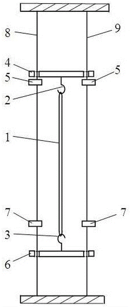
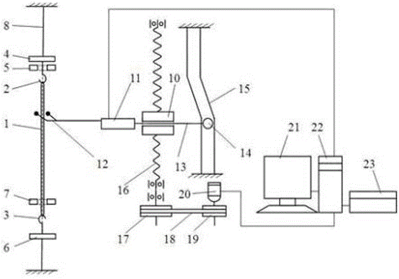
[0030] see figure 1 -3. The invention discloses a test device for thermal shrinkage rate of chemical fiber filaments. Such as figure 1 As shown, the main innovation of the present invention is that it includes a double limiter structure and a load cell 11; the double limiter structure includes 1, an upper hook 2, a lower hook 3, an upper hook plate 4, and an upper limiter 5 , the lower hook plate 6, the lower limiter 7, the metal guide wire 8, 9; the upper hook 2 is connected to the bottom of the upper hook plate 4, and the upper hook plate 4 is located above the upper limiter 5 and is limited to the upper limiter 5 slides along the metal guide wire above; the lower hook 3 is connected to the top of the lower hook plate 6, and the lower hook plate 6 is located below the lower limiter 7 and is limited to slide along the metal guide wire below the lower limiter 7; The wire fork 12 of the toggle mechanism of the load cell 11 can support the upper hook plate 4 and move upwards t...


PUM

PropertyMeasurementUnit
Perimeteraaaaaaaaaa
Lengthaaaaaaaaaa

Abstract

The invention relates to a test device and a test method for the thermal shrinkage rate of chemical fiber filaments. The test device includes a double limiter structure and a load cell; the double limiter structure includes an upper hook, a lower hook, an upper hook plate, The upper limiter, the lower hook plate, the lower limiter, and the metal guide wire; the installation of the load cell and its connected toggle mechanism can hold up the upper hook plate to move upward, and the lower hook plate moves up to the lower limiter to be moved up by it. When the upper hook plate continues to rise, tension is applied to the twisted wire sample, the load cell bears the load in the downward direction, and the instrument automatically measures the twisted wire sample under the preset standard tension before and after heating the sample Length value, so as to measure the thermal shrinkage of chemical fiber filament samples. The test device and the test method are used to significantly improve the test accuracy of the thermal shrinkage rate of the chemical fiber filament sample, the calibration and calibration of the force measuring system is convenient, the structure is reliable, and the failure rate is greatly reduced.

Description

technical field [0001] The invention belongs to the field of textile and chemical fiber measuring instruments, in particular to a test device and a test method for the thermal shrinkage rate of chemical fiber filaments, which are suitable for the quality control of chemical fiber factories and the inspection of fiber quality by textile enterprises and testing institutions. Background technique [0002] The thermal shrinkage rate of chemical fiber filament is one of the main parameters to characterize the structure and properties of the fiber. It is a comprehensive performance index related to the process of forming and post-processing of chemical fiber filament. It characterizes the dimensional stability of product post-processing and product consumption. . The thermal shrinkage rate of chemical fiber filaments is closely related to the finishing process and the dyeing performance of the product, which directly affects the wearing performance and appearance of the fabric. T...

Claims


Application Information

Patent Timeline
IPC IPC(8): G01N25/16G01D21/02
CPCG01N25/16G01D21/02
Inventor 岳朝风
Owner ANHUI LUXUN ELECTRONICS TECH
Why Eureka
Try Eureka