
Switch state detecting circuit of protective relaying device

A relay protection device and switch state technology, which is applied in the electric power field, can solve problems such as the difficulty in accurately and timely detecting abnormal switch states, and achieve the effect of avoiding non-full-phase operation and improving the reliability of power supply

Active Publication Date: 2016-10-12
ZHEJIANG NANRUI ELECTRIC POWER AUTOMATION
View PDF5 Cites 7 Cited by
  • Summary
  • Abstract
  • Description
  • Claims
  • Application Information

AI Technical Summary

Problems solved by technology

[0004] The technical problem to be solved by the present invention is to overcome the defect that it is difficult to accurately and timely detect the abnormal switch state when the switch of the existing relay protection device changes due to abnormal tripping and other reasons

Method used


Image

  • Switch state detecting circuit of protective relaying device
  • Switch state detecting circuit of protective relaying device
  • Switch state detecting circuit of protective relaying device

Examples


Embodiment Construction

[0038] The technical solutions of the present invention will be clearly and completely described below in conjunction with the accompanying drawings. Apparently, the described embodiments are some of the embodiments of the present invention, but not all of them. Based on the embodiments of the present invention, all other embodiments obtained by persons of ordinary skill in the art without making creative efforts belong to the protection scope of the present invention.

[0039] In the description of the present invention, it should be noted that the terms "center", "upper", "lower", "left", "right", "vertical", "horizontal", "inner", "outer" etc. The indicated orientation or positional relationship is based on the orientation or positional relationship shown in the drawings, and is only for the convenience of describing the present invention and simplifying the description, rather than indicating or implying that the referred device or element must have a specific orientation, ...


PUM


Abstract

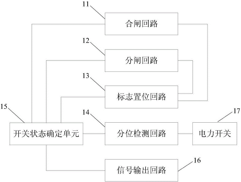
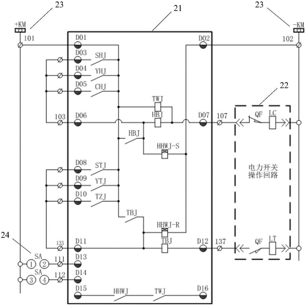
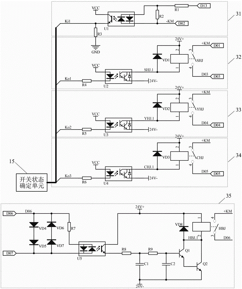
The invention provides a switch state detecting circuit of a protective relaying device. The switch state detecting circuit comprises a closing loop, an opening loop, a sign setting loop, an opening position detection loop and a switch state determination unit. Whether a switch state corresponds to a closing signal or an opening signal can be determined according to the closing signal or the opening signal of a monitored switch. When a switch switches to an opening state under a closing state without receiving an opening signal, the switch state is determined to be abnormal. When a switch with a protective relaying device is under manual operation, remote control and automatic operation models, abnormal switch state change can be accurately and timely detected once abnormal switch state change occurs due to abnormal tripping caused by switch operating mechanism fault. Non-full-phase operation, larger power failure scope and equipment damage accidents due to abnormal state of a switch can be effectively prevented, and the reliability of power supply can be improved.

Description

technical field [0001] The invention relates to the field of electric power technology, in particular to a switch state detection circuit of a relay protection device. Background technique [0002] In the relay protection device of the power system, the traditional relay protection is generally limited to the local manual operation of the switch. The traditional relay protection circuit generally has six sets of contacts of "pre-close, close, after close, pre-open, open, after open", among which the "after close" and "after open" contacts have free strokes, which can be moved between the switches. It is in a self-holding state after the closing or opening operation, and it cannot be opened or closed until there is a reverse manual operation. In general wiring, the "closed" contact is connected in series with the "divided" auxiliary contact of the switch to form a signal circuit that does not correspond to the switch position. After the switch is closed, if there is a fault...

Claims


Application Information

Patent Timeline
Patent Type & Authority Applications(China)
IPC IPC(8): G01R31/327
CPCG01R31/3278
Inventor 郭锋丁凌云
Owner ZHEJIANG NANRUI ELECTRIC POWER AUTOMATION
Learn More