Motion platform

A motion platform and motion technology, applied in the field of motion platforms, can solve problems such as dynamic performance, poor reliability and stability of motion platforms, overheating of linear motors, asymmetrical mechanical structures, etc., to improve reliability and stability, and increase motion speed , Improve the effect of dynamic performance

Inactive Publication Date: 2016-10-12
GUANGDONG UNIV OF TECH
View PDF11 Cites 0 Cited by
  • Summary
  • Abstract
  • Description
  • Claims
  • Application Information

AI Technical Summary

Problems solved by technology

[0002] With the continuous advancement of science and technology, the motion platform needs to be faster and more accurate, which puts forward higher requirements for the driving structure of the motion platform, and the existing motion platform mainly has two driving methods, one is to use the traditional Rotary motor drive mode, which is limited by machining accuracy, inertia, stiffness, wear and other factors, cannot meet the required high speed and high precision requirements; the other is to drive the motion platform through a linear motor, Compared with the above-mentioned rotary motor drive method, a series of transmission mechanisms for converting rotary motion into linear motion are omitted, and the response speed, running speed and accuracy have been greatly improved. Under the above structure, the motion platform is improved. If the speed needs to be increased, the current needs to be increased, which will lead to an increase in the heat generated by the linear motor. However, due to the constraints of heat dissipation and structural design of the linear motor itself, after the speed of the motion platform reaches a certain level, continuing to increase will cause the linear motor to overheat. , it is easy to cause damage to the linear motor, and even cause safety accidents, and when the load is loaded, due to the asymmetrical mechanical structure, the force point is located on one side of the motion platform, resulting in poor dynamic performance, reliability and stability of the motion platform, which limits the high-speed Development of the sports platform

Method used


Image

  • Motion platform
  • Motion platform
  • Motion platform

Examples


Embodiment Construction

[0026] The invention provides a motion platform to achieve the purposes of increasing its running speed, improving its dynamic performance, and improving its reliability and stability.

[0027] The following will clearly and completely describe the technical solutions in the embodiments of the present invention with reference to the accompanying drawings in the embodiments of the present invention. Obviously, the described embodiments are only some, not all, embodiments of the present invention. Based on the embodiments of the present invention, all other embodiments obtained by persons of ordinary skill in the art without making creative efforts belong to the protection scope of the present invention.

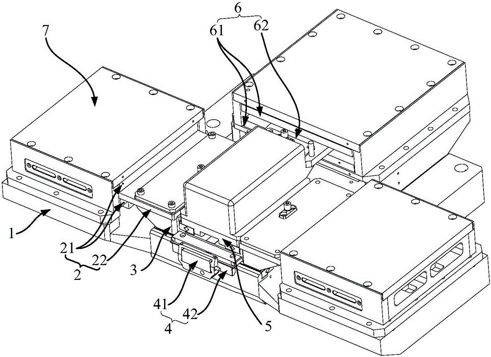
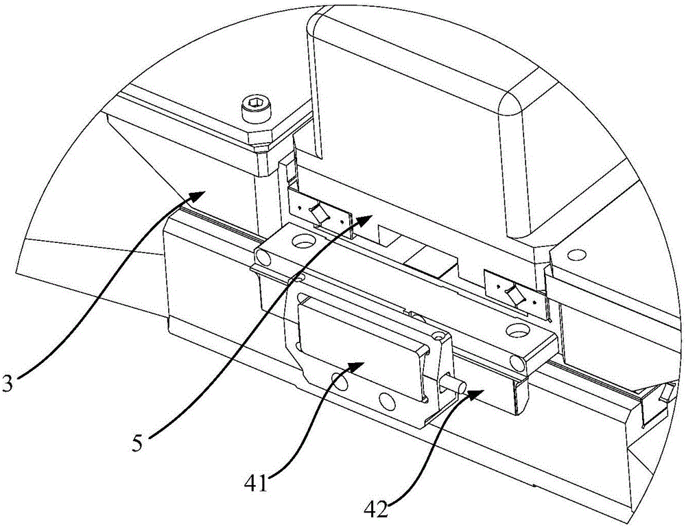
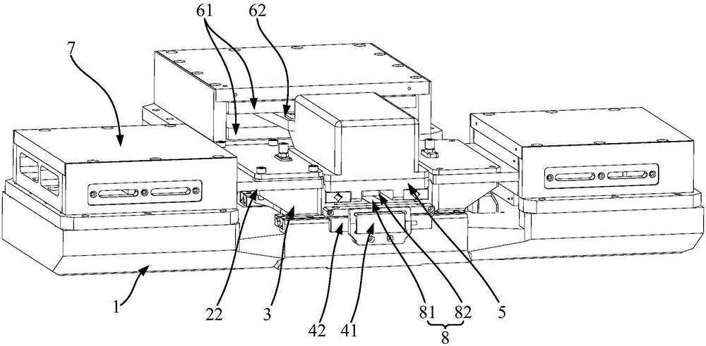
[0028] see Figure 1-Figure 3 , figure 1 It is a schematic diagram of the structure of the motion platform provided by the embodiment of the present invention under a viewing angle, figure 2 for figure 1 The schematic diagram of the local structure, image 3 It is a schem...


PUM


Abstract

The present invention discloses a motion platform, which comprises a base, a bearing platform and at least two first linear motors. The bearing platform is capable of conducting the reciprocating linear motion on the base. The at least two first linear motors together drive the bearing platform to move. At least one first linear motor is located at one end of the moving track of the bearing platform, and the rest first linear motors are located at the other end of the moving track of the bearing platform. The above moving platform is respectively provided with at least one first linear motor at the two ends of the moving track of the bearing platform, so that the bearing platform is driven to move simultaneously by the first linear motors at the two ends thereof. Compared with the prior art, on the premise that the input current is maintained the same, the bearing platform is larger in acceleration, so that the desired speed can be realized more quickly. During the moving speed increasing process, the overheating phenomenon of the linear motors is avoided at the same time. Both the two ends of the bearing platform are provided with force bearing points. In this way, loads and the variation of load positions are applied to the at least two first linear motors, so that the dynamic performance thereof is improved. Meanwhile, the reliability and the stability are improved.

Description

technical field [0001] The invention relates to the technical field of sports platforms, in particular to a sports platform. Background technique [0002] With the continuous advancement of science and technology, the motion platform needs to be faster and more accurate, which puts forward higher requirements for the driving structure of the motion platform, and the existing motion platform mainly has two driving methods, one is to use the traditional Rotary motor drive mode, which is limited by machining accuracy, inertia, stiffness, wear and other factors, cannot meet the required high speed and high precision requirements; the other is to drive the motion platform through a linear motor, Compared with the above-mentioned rotary motor drive method, a series of transmission mechanisms for converting rotary motion into linear motion are omitted, and the response speed, running speed and accuracy have been greatly improved. Under the above structure, the motion platform is im...

Claims


Application Information

Patent Timeline
Patent Type & Authority Applications(China)
IPC IPC(8): G05D3/12
CPCG05D3/125
Inventor 贺云波陈新吴晓明曾志平高健杨志军陈云张昱汤晖熬银辉
Owner GUANGDONG UNIV OF TECH
Why Eureka
Try Eureka