Banknote processing apparatus

A banknote processing device and banknote technology, which is applied to the device for accepting coins, handling coins or valuable banknotes, instruments, etc., can solve the problem of not getting a relatively large compression, banknotes are easy to hit other parts, and product design is more difficult and other problems, to achieve the effect of simplifying the overall layout, high production cost, and simplifying the structure

Active Publication Date: 2016-10-12
广州智清电子科技有限公司
View PDF10 Cites 22 Cited by
  • Summary
  • Abstract
  • Description
  • Claims
  • Application Information

AI Technical Summary

Problems solved by technology

But still there are following problems in this technical scheme: 1) temporary storage part is positioned at the below of deposit and withdrawal port, and the height of equipment= deposit and withdrawal port height+temporary storage part height+transmission channel height+paper money storage box height, this height has not yet A larger compression is obtained; 2) The banknotes in the temporary storage part are lifted to the deposit and withdrawal port by a lifting mechanism, and the banknote receiving mechanism of the deposit and withdrawal port receives the banknotes. This process is cumbersome and takes a long time to respond; 3) The whole stack During the lifting process of the banknotes, the banknotes are easy to hit other parts, causing failures, especially when the loaded banknotes are full and the banknotes have defects such as wrinkles, fluff, tears, etc., such failures are prone to occur; 4) Temporary storage and lifting Too many action mechanisms such as mechanism, deposit and withdrawal mechanism and corresponding banknote receiving mechanism are concentrated in the same area of ​​the equipment, resulting in a very compact local space and increasing difficulty in product design, which is not conducive to improving product reliability.

Method used


Image

  • Banknote processing apparatus
  • Banknote processing apparatus
  • Banknote processing apparatus

Examples


Embodiment Construction

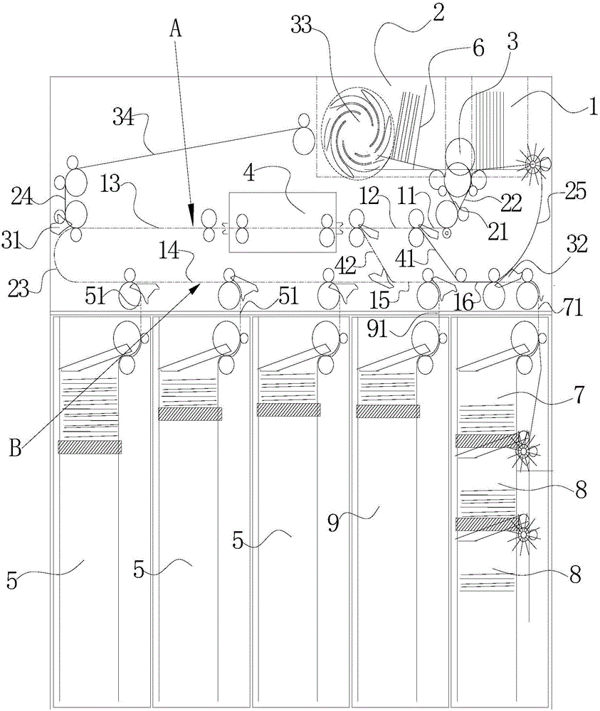
[0035] The present invention will be further described below in conjunction with the accompanying drawings. The description of the orientation in Chinese is as follows figure 1 as standard.

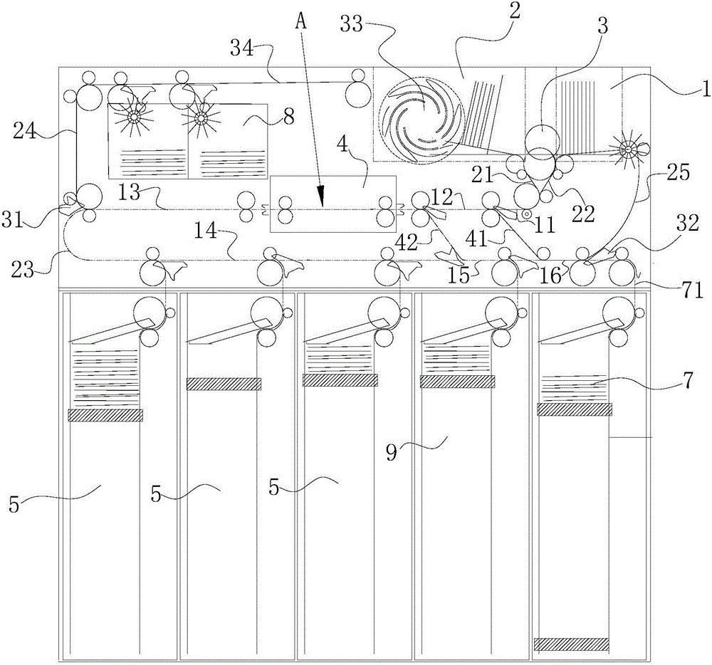
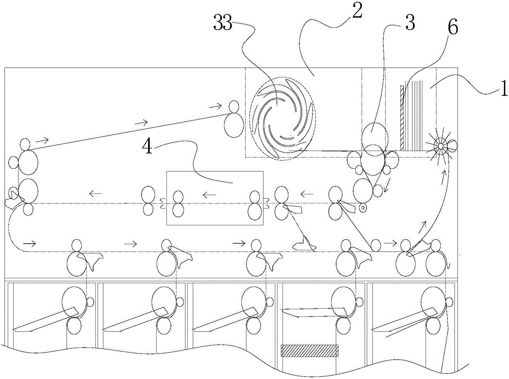
[0036] Such as figure 1 and figure 2 As shown, a banknote processing device includes a deposit and withdrawal port 1, a banknote identification part 4, a temporary storage part 2, at least one currency storage box 5, and an upper transmission channel A, a lower transmission channel B and a temporary banknote transport channel A for transporting banknotes. storage transmission channel 34, wherein, the upper transmission channel A includes the first transmission channel 11, the second transmission channel 12 and the third transmission channel 13 connected in sequence, and the lower transmission channel includes the fourth transmission channel 14, the third transmission channel 13 connected in sequence The fifth transmission channel 15 and the sixth transmission channel 16, the detection...


PUM


Abstract

The invention discloses a banknote processing apparatus. The banknote processing apparatus comprises a deposit and withdrawal port, a banknote identification portion, a temporary storage portion, at least one banknote storage box, and an upper transmission channel, a lower transmission channel and a temporary storage transmission channel which are used for carrying banknotes, wherein the temporary storage portion is arranged at the rear side of the deposit and withdrawal port, the front end of the upper transmission channel is connected with an outlet end of the temporary storage portion and an outlet end of the deposit and withdrawal port, the front end of the lower transmission channel is connected with an inlet end of the deposit and withdrawal port, the front end of the temporary storage transmission channel is connected with an inlet end of the temporary storage portion, the banknote identification portion is installed on the upper transmission channel, and the banknote storage box is connected with the lower transmission channel. The structure is simple, the overall layout of the whole machine is simplified, the effect of flattening and straightening the channels is realized, the effects of reducing banknote stagnation and reducing noise are obvious, and through arrangement of the cyclic transmission channels, the transmission processing time of the banknotes is greatly reduced.

Description

technical field [0001] The invention relates to a banknote processing device used for depositing and withdrawing money of an automatic teller machine. Background technique [0002] ATM provides great convenience for users to withdraw cash, ATM can serve 24 hours a day; and people do not need to line up at the counter to withdraw cash, which greatly reduces the workload of bank tellers. In recent years, with the advancement of technology, the ATM CRS has gradually become the mainstream of self-service equipment. CRS can withdraw the cash deposited by users for other users to withdraw. This kind of cash deposit and withdrawal equipment greatly reduces the need for banks to clear and add money. The workload, especially when the amount of deposits and withdrawals are relatively close, can last for several months without manual intervention, bringing obvious economic benefits to the bank. With the continuous development of technology, the current deposit and withdrawal cycle equ...

Claims


Application Information

Patent Timeline
Patent Type & Authority Applications(China)
IPC IPC(8): G07D11/00
CPCG07D11/13G07D11/18
Inventor 吴恩张晓生廖任
Owner 广州智清电子科技有限公司
Why Eureka
Try Eureka