High-speed wrapping machine

A wrapping machine, high-speed technology, applied in the direction of electrical components, circuits, conductor/cable insulation, etc., to achieve the effect of good performance, not easy to loosen, and simple adjustment

Inactive Publication Date: 2016-10-12
WUHU ELECTROTECHN MACHINERY
View PDF6 Cites 15 Cited by
  • Summary
  • Abstract
  • Description
  • Claims
  • Application Information

AI Technical Summary

Problems solved by technology

[0003] The purpose of the present invention is to provide a high-speed wrapping machine to solve the problem of adjusting th

Method used


Image

  • High-speed wrapping machine
  • High-speed wrapping machine
  • High-speed wrapping machine

Examples


Example Embodiment

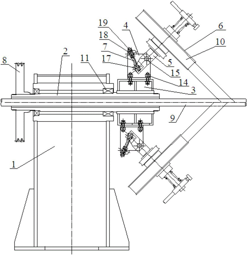
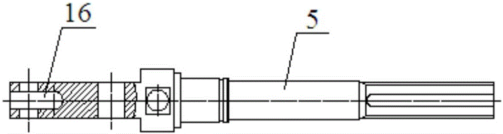
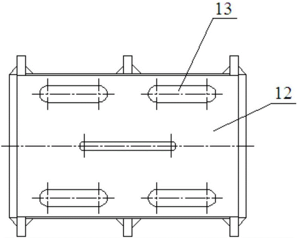
[0022] Refer to the attached drawings, a high-speed wrapping machine includes a wrapping support 1 on which a hollow main shaft 2 arranged horizontally is rotatably installed. The right end of the hollow main shaft 2 is installed with a rotating bracket 3, which surrounds the rotating bracket 3 respectively. A plurality of installation planes 12 are provided, and a plurality of support frames 4 are respectively installed; a plurality of reel shafts 5 arranged in an inclined manner are provided, and a reel 6 is installed in the middle of the plurality of reel shafts 5. The rear part of the shaft 5 is respectively mounted on a plurality of support frames 4 corresponding to rotation, and the plurality of support frames 4 are respectively installed with adjusting screws 7, and the rear ends of the adjusting screws 7 are respectively connected to the rear of the reel shafts rotatably installed on the supporting frame. The left end of the hollow main shaft 2 is equipped with a pulley ...


PUM


Abstract

The invention discloses a high-speed wrapping machine. The high-speed wrapping machine comprises a wrapping support and a hollow main shaft, the right end of the hollow main shaft is provided with a rotation support, multiple installation planes are respectively arranged around the rotation support, and multiple support frames are respectively installed on the installation planes; and the high-speed wrapping machine comprises multiple aslant arranged reel shafts, the central portions of the multiple reel shafts are each provided with a reel, the rear portions of the multiple rear shafts are respectively correspondingly rotationally installed on the multiple support frames, the multiple support frames are each provided with an adjustment screw rod, and the rear ends of the adjustment screw rods are respectively in rotational connection with the rear ends of the reel shafts rotationally installed on the support frames. The application performance is good, the adjustment is simple, the locking is reliable, the safety is high, the rigidity of the rotation support is high, during high-speed rotation, loosening is not easily generated, the problem of adjustment of the angle of a wrapping band in a wire and cable production process and the pitch problem of coverage of multiple wrapping bands are solved, the production efficiency is improved, and the high-speed wrapping machine is suitable for a wrapping machine rotating at a high speed.

Description

Technical field [0001] The invention relates to the field of wrapping machines, in particular to a high-speed wrapping machine. Background technique [0002] In the production process of wire and cable, the taping angle of the existing wrapping machine is adjusted by a worm helical gear, which is self-locking by itself and has no locking mechanism. The reel shaft cannot rotate at a high speed, and the safety is poor; the left and right sides of the reel shaft The adjustment is by clamping on the guide shaft. The rigidity of the system is poor. When the wrapping machine starts and brakes, the stability of the rotating body is not good, which affects the performance of the wrapping machine. Summary of the invention [0003] The purpose of the present invention is to provide a high-speed wrapping machine to solve the problem of adjusting the angle of the wrapping tape and the pitch of the multi-strand wrapping tape during the wire and cable production process. [0004] The technical s...

Claims


Application Information

Patent Timeline
IPC IPC(8): H01B13/10H01B13/26
CPCH01B13/10H01B13/2613
Inventor 孙健王钟张登坪吴旭东陈操曾俊梅王松强
Owner WUHU ELECTROTECHN MACHINERY
Why Eureka
Try Eureka