
Cantilever type inertia switch

An inertial switch and cantilever beam technology, applied in the field of inertial switches, can solve the problems of large size, high production cost, long response time, etc., and achieve the effect of broad application prospects, light weight and small size

Inactive Publication Date: 2016-10-12
湖北三江航天红林探控有限公司
View PDF8 Cites 5 Cited by
  • Summary
  • Abstract
  • Description
  • Claims
  • Application Information

AI Technical Summary

Problems solved by technology

However, the traditional inertial switch can only realize the closing function in one direction, and has the disadvantages of wide conduction threshold range, low precision, and long response time
In addition, the traditional inertia switch is limited by the mechanical processing technology level, especially the spring winding technology level, and has the disadvantages of large volume, long debugging period, and high production cost.

Method used


Image

  • Cantilever type inertia switch

Examples


Embodiment Construction

[0013] Below in conjunction with accompanying drawing and specific embodiment the present invention is described in further detail:

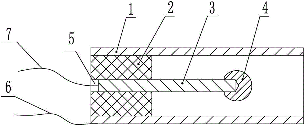
[0014] A cantilever beam type inertia switch shown in the figure includes a hollow cylindrical shell 1, an insulating seat 2, an electrode rod 3, and a spherical contact 4, and the insulating seat 2 is fixed at one end of the inner cavity of the cylindrical shell 1 The middle part of the insulating seat 2 is provided with a through hole 5, one end of the electrode rod 3 is embedded in the through hole 5 and fixedly connected with the insulating seat 2, and the other end of the electrode rod 3 extends outward along its axial direction through the through hole 5 and is suspended in the The middle part of the inner cavity of the cylindrical housing 1 is fixedly connected with the spherical contact 4 . The maximum external dimension of the cylindrical housing 1 is Φ6mm×14mm, and the designed reliable closed overload value ranges from 110g to 200g. ...


PUM


Abstract

The invention discloses a cantilever type inertia switch. The cantilever type inertia switch comprises a hollow cylindrical shell, an insulating base, an electrode stem and a spherical contact, and is characterized in that the insulating base is fixed at one end of an inner cavity of the cylindrical shell, the middle part of the insulating base is provided with a through hole, one end of the electrode stem is embedded into the through hole and fixedly connected with the insulating base, the other end of the electrode stem extends outward along the axial direction thereof, passes through the through hole and is suspended at the middle part of the inner cavity of the cylindrical shell, and the electrode stem is fixedly connected with the spherical contact. The inertia switch disclosed by the invention can overcome resistance of the electrode stem under an overload action in any directions except for the axial direction so as to carry out deflection movements until being contacted with the cylindrical shell, the inertia switch is closed, and an ignition control circuit is connected. The cantilever type inertia switch has a universal closing function, thereby solving a key technology for reliably triggering a hard target against fuse under a large striking angle condition, and enabling the fuse to act reliably under various missile and target intersection conditions.

Description

technical field [0001] The invention relates to the technical field of inertial switches, in particular to a cantilever beam type inertial switch. Background technique [0002] Inertial switch is an important component commonly used in anti-hard target fuzes. It is mainly used to identify the information of the warhead hitting the target and control the working state of the fuze firing control circuit. When the warhead hits the target, the inertial switch feels the impact overload and closes, triggering or conducting the ignition control circuit of the fuze, allowing the charged ignition power to discharge the first electric pyrotechnic product to complete the detonation function. [0003] The traditional inertia switch adopts the design scheme of spring and mass block, and the mass block acts as a moving electrode, which compresses the spring under the action of impact overload until it contacts with the other pole to close the switch. However, the traditional inertial swi...

Claims


Application Information

Patent Timeline
Patent Type & Authority Applications(China)
IPC IPC(8): H01H35/14
CPCH01H35/14
Inventor 王林魏梦颖唐璋
Owner 湖北三江航天红林探控有限公司
Learn More