Electrical junction box

A technology of electrical junction boxes and electrical connection components, which is applied in the direction of electrical components, circuits or fluid pipelines, vehicle components, etc., and can solve problems such as circuit board failures

Active Publication Date: 2016-10-12
SUMITOMO WIRING SYST LTD +1
View PDF10 Cites 0 Cited by
  • Summary
  • Abstract
  • Description
  • Claims
  • Application Information

AI Technical Summary

Problems solved by technology

[0004] Since the above case includes ventilation holes, foreign matter such as bugs or dust can enter the case through the ventilation holes, which may cause circuit board failure

Method used


Image

  • Electrical junction box
  • Electrical junction box
  • Electrical junction box

Examples


Embodiment

[0039] 1. The overall structure of the electrical junction box

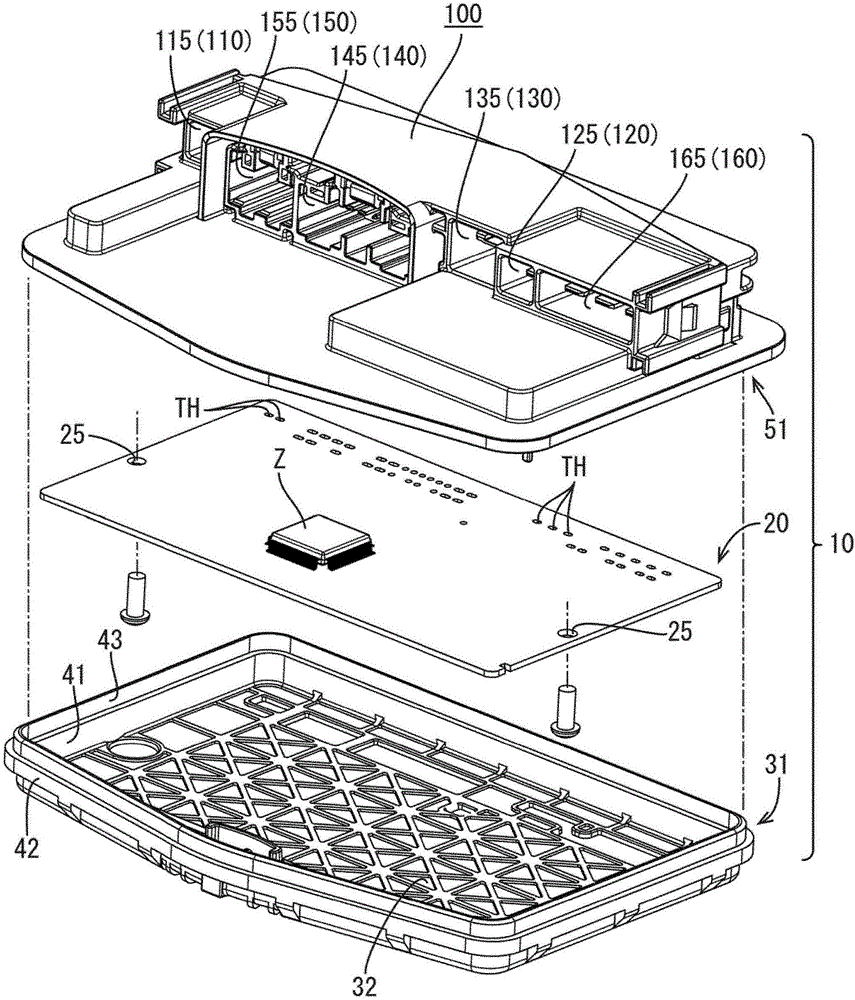
[0040] Reference below Figure 1 to Figure 12 The electrical junction box 10 for a vehicle is described.

[0041] Such as figure 1 As shown, the electrical junction box 10 includes a circuit board 20 and a housing 30 . The circuit board 20 includes a printed circuit board and electronic components Z mounted on the printed circuit board. The circuit board 20 has a rectangular shape, and includes conductive wires (not shown) formed using a wire printing technique. A moisture-proof insulating coating is applied to the circuit board 20 after the electronic components Z are mounted thereon. For example, liquid resin is sprayed on the circuit board 20 to form a thin film on the circuit board 20 . Moisture does not affect the electrical performance of the circuit board 20 due to the coating.

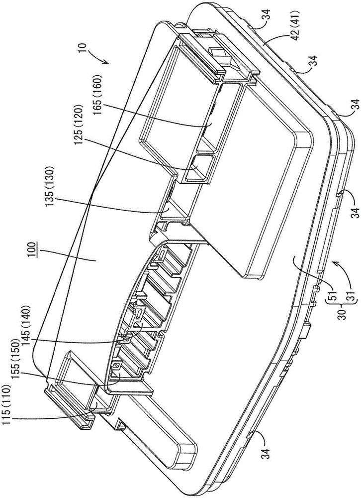
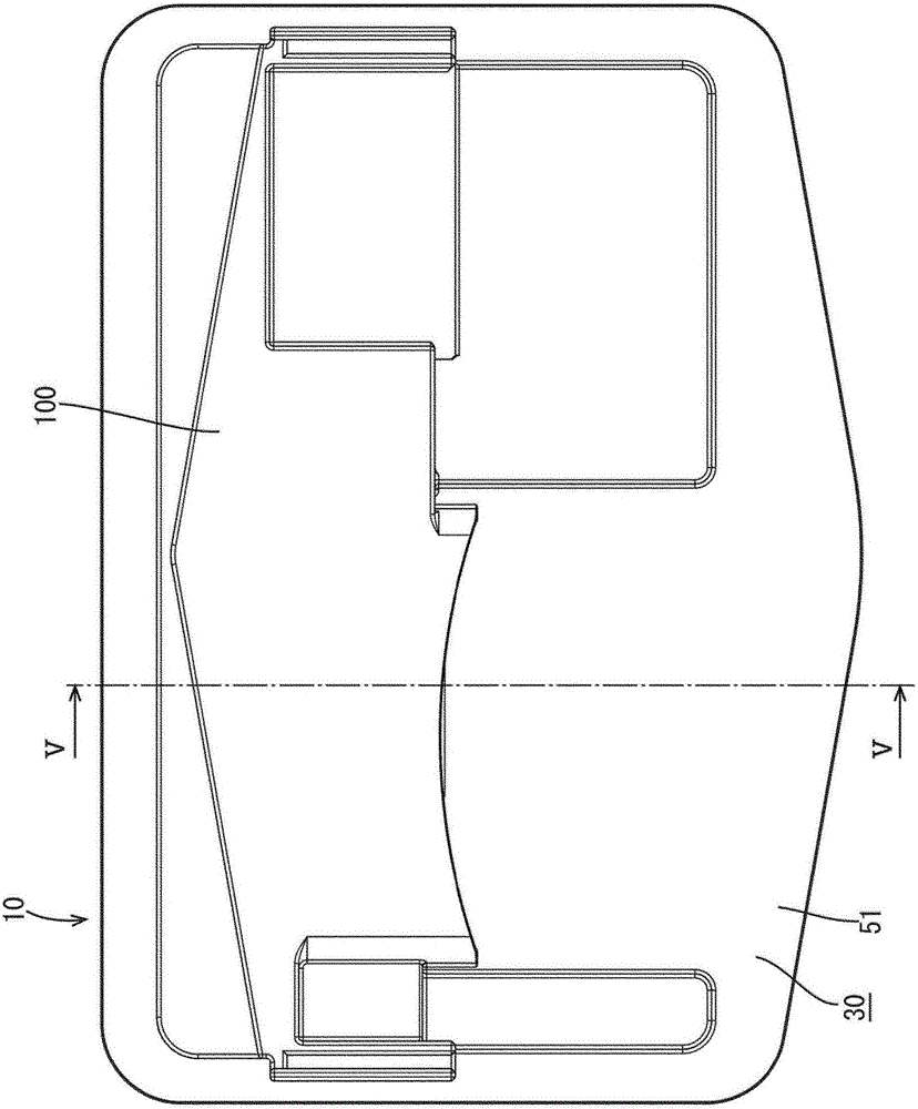
[0042] The housing 30 holds the circuit board 20 therein. The case 30 includes a holding member (case element) 31 and a c...


PUM


Abstract

An electrical junction box includes a circuit board and a case. The case holds the circuit board therein. The case includes case components bonded to each other such that the case components are liquid-tight to each other. One of the case components includes a connector portion that is liquid-tight to another portion of the one of the case components. The connector portion includes a hood portion to which a mating connector is to be connected. The hood portion includes a ventilation hole that communicates with internal space of the case.

Description

technical field [0001] The present disclosure relates to an electrical junction box. Background technique [0002] A conventional electrical junction box includes a circuit board accommodated in a circuit case having ventilation holes. The part of the case other than the ventilation hole is liquid-tight. According to this configuration, the waterproofness of the electrical junction box is improved while maintaining air permeability. Such an electrical junction box is disclosed in Patent Document 1. [0003] Patent Document 1: Japanese Unexamined Patent Publication No. 2011-239560 [0004] Since the above-mentioned case includes a vent hole, foreign matter such as bugs or dust may enter into the case through the vent hole, thereby possibly causing malfunction of the circuit board. [0005] The present invention has been accomplished in view of the above circumstances. It is an object of the present invention to provide an electrical junction box having a structure for re...

Claims


Application Information

Patent Timeline
IPC IPC(8): H01R13/52H02G3/08
CPCH01R13/52H02G3/08H02G3/088B60R16/0238
Inventor 谷口贵之小牧和也伊藤二郎
Owner SUMITOMO WIRING SYST LTD
Why Eureka
Try Eureka