[0020] In order to make it easy to understand the technical means, creative features, objectives and effects achieved by the present invention, the present invention will be further explained below in conjunction with specific drawings.
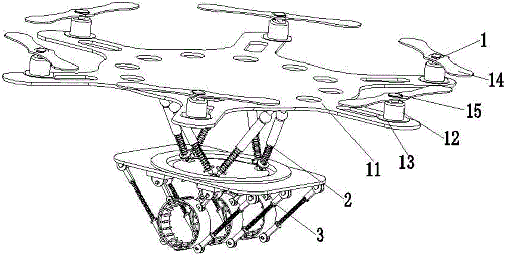
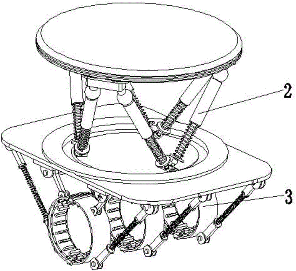
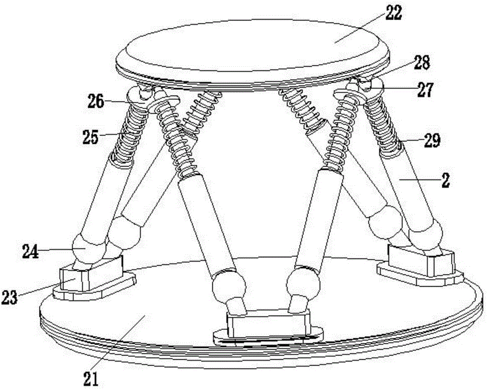
[0021] Such as Figure 1 to Figure 6 As shown, an electric power transmission line deicing aircraft includes a drone body 1, a six-degree-of-freedom parallel mechanism 2 and a deicing device 3; the six-degree-of-freedom parallel mechanism 2 is located in the drone body 1 and the deicing device 3, and the upper end of the six-degree-of-freedom parallel mechanism 2 is connected with the drone body 1, and the lower end of the six-degree-of-freedom parallel mechanism 2 is connected with the deicing device 3.
[0022] Such as figure 1 As shown, the drone body 1 includes a frame 11, a servo motor 12, a motor support 13, a propeller 14 and a locking buckle 15, and the servo motor 12, a motor support 13, a propeller 14 and a locking buckle 15 The number of the frame 11 is two; the outer side of the frame 11 is uniformly and symmetrically provided with brackets along its central axis, the center of the frame 11 is evenly provided with a material reduction hole, and the lower end of the frame 11 is provided with an upper installation threaded hole, The servo motor 12 is fixed on the front end of the frame 11 through the motor support 13, the propeller 14 is installed on the main shaft of the servo motor 12, and the propeller 14 and the main shaft of the servo motor 12 are locked and fixed by the locking buckle 15; by the servo motor The rotation of 12 drives the rotation of the propeller 14, thereby generating lift, thereby providing power support for the aerial operations of the present invention.
[0023] Such as figure 2 with image 3 As shown, the six-degree-of-freedom parallel mechanism 2 includes a fixed platform 21, a movable platform 22, a connecting seat 23, an upper spherical hinge 24, an electric push rod 25, a stop plate 26, a lower spherical hinge 27, a triangular seat 28 and a limiter. Position spring 29; the number of the connecting seat 23 and the triangle seat 28 is three, the number of the upper spherical hinge 24, the electric push rod 25, the stop plate seat 26 and the lower spherical hinge 27 are all six, the fixed platform 21 and The movable platform 22 is a disc-shaped structure, and the movable platform 22 is located directly below the fixed platform 21. The upper end part of the fixed platform 21 and the lower end part of the movable platform 22 are respectively provided with mounting threads, and the connecting seat 23 is installed on the lower end surface of the fixed platform 21 The connecting seat 23 is arranged in a regular triangle position on the fixed platform 21, the triangular seat 28 is installed on the upper end surface of the movable platform 22, and the installation positions between the connecting seat 23 and the triangular seat 28 are staggered in pairs, and the triangular seat 28 is in a straight Triangular column structure, the triangle seat 28 is respectively symmetrically provided with inclined surfaces along its vertical centerline. The inclined surfaces are provided with installation threaded holes matching the lower end external threads of the lower spherical hinge 27. The bottom end of the electric push rod 25 passes through the upper spherical hinge. 24 is connected to the connecting seat 23, the top end of the electric push rod 25 is connected to the upper end of the stop plate 26, the lower end of the stop plate 26 is connected to one end of the lower spherical hinge 27, and the other end of the lower spherical hinge 27 is installed on the triangle seat 28 to limit The position spring 29 is wound and sleeved on the electric push rod 25, and one end of the limit spring 29 is connected with the electric push rod 25, and the other end of the limit spring 29 is connected with the block seat 26; the 6-DOF parallel mechanism 2 adopts 6-SPS The six-degree-of-freedom parallel mechanism is more rigid than the series mechanism. The six-degree-of-freedom parallel mechanism 2 has stable structure, high movement flexibility, strong bearing capacity and high micro-motion accuracy. The six-degree-of-freedom parallel mechanism 2 can perform three A total of six degrees of freedom movement in translation and three rotations, and the movement space is small, the movement speed is fast, and the movement flexibility is good. In the present invention, the six-degree-of-freedom parallel mechanism 2 drives the entire deicing device 3 in space. A total of six degrees of freedom movement in translation and three rotations is convenient for the precise micro-size and orientation adjustment of the deicing device 3 during the deicing operation of the overhead transmission line, and convenient for the mobile operation and flexible operation of the present invention during the deicing operation of the transmission line Therefore, the damage to the transmission line itself caused by the present invention during the deicing operation is reduced.
[0024] Such as figure 2 , Figure 4 , Figure 5 with Image 6 As shown, the deicing device 3 includes a connecting platform 31 and a deicing mechanism 32, and the number of deicing mechanisms 32 is six, the lower end of the connecting platform 31 is a square plate structure, the upper end of the connecting platform 32 is a cylindrical structure, and the connection The upper end surface of the platform 31 is provided with a lower installation threaded hole which is matched and connected with the lower end installation thread part of the movable platform 22, which facilitates the disassembly and installation of the present invention through a threaded connection. The deicing mechanism 32 is located below the connecting platform, and the deicing mechanism 32 are arranged symmetrically in pairs along the transverse center axis of the connecting platform 31; the deicing mechanism 32 includes an adjusting rail 321, an adjusting guide block 322, a first ear seat 323, a first rotating shaft 324, a first connecting rod 325, The second ear seat 326, the second rotating shaft 327, the deicing claw 328, the third ear seat 329, the third rotating shaft 3210, the upper support rod 3211, the tension spring 3212, the lower support rod 3213, the fourth ear seat 3214 and the fourth Rotating shaft 3215; the left and right ends of the adjusting rail 321 are respectively provided with baffles, the adjusting guide block 322 is installed on the adjusting rail 321, the first ear 323 is fixed on the adjusting guide block 322, the upper end of the first connecting rod 325 passes through the A rotating shaft 324 is installed on the first ear seat 323, the lower end of the first connecting rod 325 is installed on the second ear seat 326 through the second rotating shaft 327, and the second ear seat 326 is fixed on the outer surface of the upper right end of the deicing claw 328, The upper end of the upper support rod 3211 is mounted on the third ear seat 329 through the third rotating shaft 3210, the tension spring 3212 is located between the upper support rod 3211 and the lower support rod 3213, and one end of the tension spring 3212 is connected to the lower end of the upper support rod 3211, The other end of the spring 3212 is connected with the upper end of the lower support rod 3213, the lower end of the lower support rod 3213 is mounted on the fourth ear seat 3214 through the fourth shaft 3215, and the fourth ear seat 3214 is fixed on the outer surface of the lower right end of the deicing claw 328; The deicing pawl 328 includes a fixing frame 3281, positioning block 3282, deicing pawl 3283, and a vibrating rod 3284; the fixing frame 3281 has a semicircular ring structure, and a mounting cavity is provided inside the fixing frame 3281, and the positioning block 3282 The number is two. The positioning blocks 3282 are respectively fixed on the upper and lower ends of the fixing frame 3281. The number of deicing claws 3283 and vibrating rods 3284 is not less than ten. The deicing claws 3283 are located inside the fixing frame 3281, and the deicing claws 3283 are along the fixing frame 3281. The central axis of the deicing claw 3283 is evenly arranged in the circumferential direction. The rear end of the deicing claw 3283 is provided with an "Ω" groove, and the back end of the deicing claw 3283 is installed inside the mounting cavity inside the fixing frame 3281. The front end of the deicing claw 3283 is tapered. The deicing pawl 3283 is made of stainless steel, and the vibrating rod 3284 is installed in the "Ω" groove at the back end of the deicing pawl 3283; for specific operations, first adjust the deicing mechanism 32 installed in two opposite directions to the open state, and then start it The servo motor 12 drives the rotation of the propeller 14 through the rotation of the servo motor 12, thereby driving the flight of the present invention. When the deicing device 3 approaches the deicing When the power transmission line is used, the deicing mechanism 32 is clamped on the outside of the power transmission line, and then the adjusting guide rail 321 and the adjusting guide block 322 are activated to make the deicing mechanism 32 installed in opposite directions move inward synchronously. When the deicing pawl 3283 touches the ice When the surface of the block is activated, the vibrating rod 3284 is activated, and the vibration of the deicing pawl 3283 is driven by the vibration of the vibrating rod 3284, and the front end of the deicing pawl 3283 has a tapered structure, which is more conducive to the breaking of ice, and the deicing mechanism 32 uses vibration to break The way to crush the ice on the overhead transmission line, the deicing effect is good, and the position of the deicing mechanism 32 is adjustable, which can be adapted to the deicing operation of the overhead transmission line with different icing thickness and different thickness, at the same time through the positioning block The 3282 can prevent the deicing claw 3283 from damaging and destroying the outer surface of the transmission line itself, so that the deicing device 3 has high safety, obvious deicing effect and strong working stability during deicing operation.
[0025] The above shows and describes the basic principles, main features and advantages of the present invention. Those skilled in the industry should understand that the present invention is not limited by the above embodiments. The above embodiments and the description in the specification only illustrate the principles of the present invention. Without departing from the spirit and scope of the present invention, the present invention will also There are various changes and improvements, and these changes and improvements fall within the scope of the claimed invention. The scope of protection claimed by the present invention is defined by the appended claims and their equivalents.