Eureka AIR delivers breakthrough ideas for toughest innovation challenges, trusted by R&D personnel around the world.

Concentrating photovoltaic power generation system driving arm

A power generation system and concentrated photovoltaic technology, applied in the field of solar power generation, can solve the problems of large pulling force, motor damage, poor system stability, etc., and achieve the effect of reducing pulling force and increasing stability

Inactive Publication Date: 2016-10-12
成都聚合追阳科技有限公司
View PDF3 Cites 0 Cited by
  • Summary
  • Abstract
  • Description
  • Claims
  • Application Information

AI Technical Summary

Problems solved by technology

[0002] The concentrated photovoltaic power generation system mainly uses the lens to gather the sun's rays to the concentrated photovoltaic cell chip, so as to achieve the purpose of power generation, that is, the entire concentrated photovoltaic power generation system will follow the sun's movement from east to west and rotate from east to west, while The weight of the entire concentrated photovoltaic power generation system increases in tons. The total weight of the power generation system is fixed and supported by the main beam. The larger the area of ​​a single concentrated photovoltaic power generation system, the larger the area of ​​a single concentrated photovoltaic power generation system. The more electricity generated, the lower the cost of power generation. At present, all the installations on the market are small and medium single concentrated photovoltaic power generation systems (the area of ​​a single concentrated photovoltaic power generation system is within 50 square meters), and a single concentrated photovoltaic power generation system exceeding 50 square meters Concentrating photovoltaic power generation system, at this time, close to the main beam and column to make the entire concentrated photovoltaic power generation system rotate, which will lead to particularly poor stability of the system, and will greatly reduce the service life of the entire rotating system, while the entire power generation system is running When the pulling force is very large, it is easy to damage the motor

Method used


Image

  • Concentrating photovoltaic power generation system driving arm

Examples


Embodiment Construction

[0011] The present invention will be further described below in conjunction with the accompanying drawings.

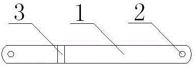
[0012] A driving arm of a concentrated photovoltaic power generation system, such as figure 1 As shown, it includes a driving arm body 1, a latch opening 2 and a hoop positioning groove 3. The latch opening 2 is located on both end faces of the driving arm body 1, and the hoop positioning groove 3 is located at 1 / 3 of the driving arm body 1. The drive arm body 1 has arc-shaped two ends and a square metal part as the main body. The arc-shaped end face will not cause any damage to the end face and the concentrated photovoltaic column or main beam during the operation of the concentrated photovoltaic power generation system. interference, the pin opening 2 is a circular through hole, which is very easy and time-saving and labor-saving when installing the pin, and the size of the hoop positioning groove 3 is consistent with the size of the hoop, so that the installation ac...


PUM


Abstract

The invention relates to a concentrating photovoltaic power generation system driving arm, and belongs to the technical field of solar power generation. The driving arm comprises a driving arm body, pin holes and a hoop positioning slot. The pin holes are respectively formed in the two end faces of the driving arm body. The hoop positioning slot is formed in a 1 / 3 position of the driving arm body. The driving arm can increase the running stability of the system. Moreover, sudden pulling force of the whole power generation system due to centre-of-gravity shift when a motor is running is reduced, and the purpose of motor protection is achieved.

Description

technical field [0001] The invention relates to a driving arm of a concentrated photovoltaic power generation system, which belongs to the technical field of solar power generation. Background technique [0002] The concentrated photovoltaic power generation system mainly uses the lens to gather the sun's rays to the concentrated photovoltaic cell chip, so as to achieve the purpose of power generation, that is, the entire concentrated photovoltaic power generation system will follow the sun's movement from east to west and rotate from east to west, while The weight of the entire concentrated photovoltaic power generation system increases in tons. The total weight of the power generation system is fixed and supported by the main beam. The larger the area of ​​a single concentrated photovoltaic power generation system, the larger the area of ​​a single concentrated photovoltaic power generation system. The more electricity is generated, the lower the cost of power generation. ...

Claims


Application Information

Patent Timeline
IPC IPC(8): H02S10/00H02S20/32
CPCH02S10/00H02S20/32Y02E10/50
Inventor 王永向
Owner 成都聚合追阳科技有限公司
Why Eureka
Eureka Blog
Learn More