Video de-interlacing method

A de-interlacing and video technology, applied in television, electrical components, image communication, etc., can solve problems such as high computational complexity and complex buffer structure

Active Publication Date: 2016-10-12
PEKING UNIV
View PDF5 Cites 6 Cited by
  • Summary
  • Abstract
  • Description
  • Claims
  • Application Information

AI Technical Summary

Problems solved by technology

The motion compensation algorithm can produce the best reconstruction quality, but its computationa

Method used


Image

  • Video de-interlacing method
  • Video de-interlacing method
  • Video de-interlacing method

Examples


Embodiment Construction

[0047] In order to make the purpose, technical solutions and advantages of the present invention clearer, the technical solutions in the embodiments of the present invention will be clearly and completely described below in conjunction with the accompanying drawings in the embodiments of the present invention. It should be understood that the specific The examples are only used to explain the present invention, not to limit the present invention. The described embodiments are only some, not all, embodiments of the present invention. Based on the embodiments of the present invention, all other embodiments obtained by persons of ordinary skill in the art without making creative efforts belong to the protection scope of the present invention.

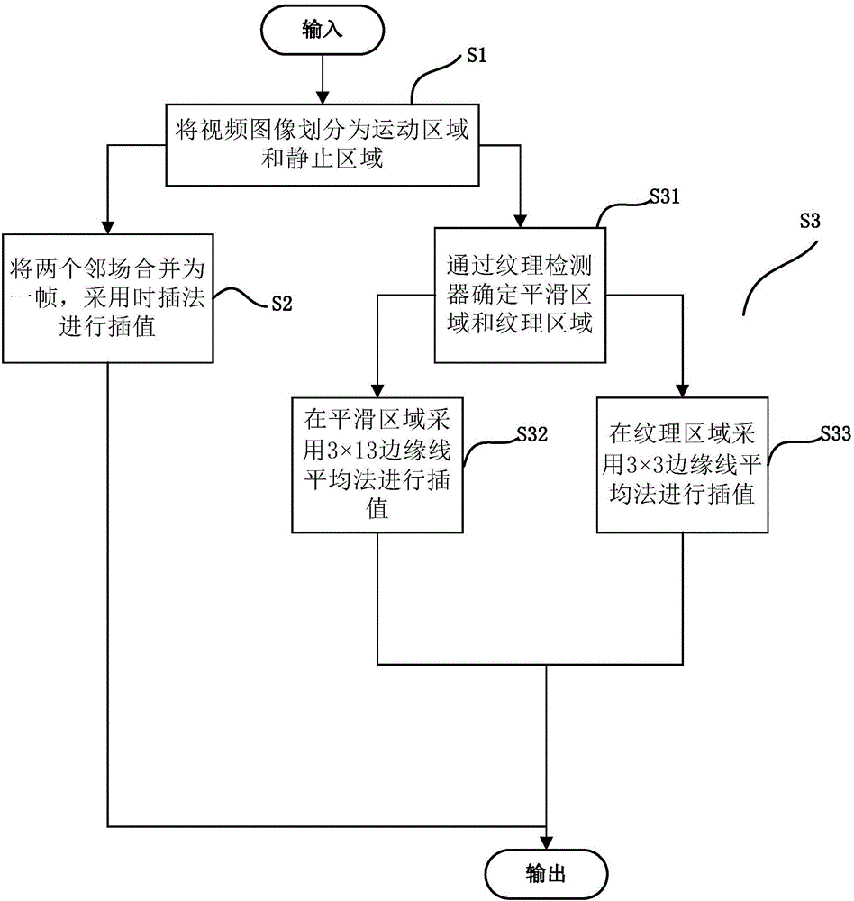
[0048] Such as figure 1 Shown, video deinterlacing method of the present invention comprises the steps:

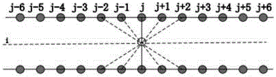
[0049] In the region division step S1, the video image is divided into a motion region and a static region by using a five-field mo...


PUM


Abstract

The invention provides a video de-interlacing method. The video de-interlacing method comprises the following steps: a regional division step: dividing a video image into a motion area and a stationary area by utilizing a five-motion detector; a stationary area interpolation step: combining two adjacent fields into one frame in the stationary area, and performing interpolation by adopting a time interpolation method; and a motion area interpolation step: performing interpolation in the motion area by adopting an enhanced edge line average method. According to the video de-interlacing method disclosed by the invention, edge-based line averaging is improved through precise motion detection; and thus, the de-interlacing effect is improved.

Description

technical field [0001] The invention belongs to the technical field of video image processing, in particular to a video deinterlacing method. Background technique [0002] Traditional video has two formats: interlaced video and progressive video. The interlaced format is widely used in broadcast television systems due to its bandwidth savings. However, interlaced scanning will bring defects such as jagged, line creep, flicker between lines, low definition, etc., and these phenomena will be more obvious in the motion area. As display devices like LCD, HDTV, UHDTV, plasma display panels, etc. require more progressive scan video, a high quality deinterlacing technique becomes more important to achieve from interlaced to progressive scan frame format conversion technology. [0003] From the prior art literature, we can see that many deinterlacing algorithms have been proposed and the existing deinterlacing algorithms can be roughly divided into two categories: intra-field de-...

Claims


Application Information

Patent Timeline
IPC IPC(8): H04N7/01
CPCH04N7/012H04N7/0142
Inventor 杨长水陈瑞贾惠柱解晓东高文
Owner PEKING UNIV
Why Eureka
Try Eureka